FAQ
Motor Failed…Who Cares?
Too often we hear maintenance & reliability experts downplay the data analysis or testing of motors that have failed from a stator fault. "Why would you need test equipment to test a stator fault?" we might hear. The mistake these "experts" make is to assume that troubleshooting a motor begins with failure analysis. Smart motors are on the market, but we haven't seen any with a big red flag that pops up with the words "STATOR FAULT" when it trips or fails to start. The reality most non-clairvoyant technicians face is they don't know exactly what failed, or if anything failed at all. Is it the motor, the load, the starter or maybe a nuisance trip? Remember a very important role of your predictive technologies is to assist the technicians in a quick recovery effort of production in the unfortunate situation of an unplanned outage. Performing some quick tests such as phase resistance, phase inductance, and ground wall tests can allow the technician to isolate quickly focus on or off of the electric motor and hasten good decision-making in deciding if a repair or replacement is necessary. A simple phase imbalance test may just prevent you from replacing a motor that doesn't need to be replaced.
It's Not Always the Motor's Fault
When testing a motor it is good practice to thoroughly test the entire motor circuit. A Wound Rotor Motor has two circuits – the stator circuit, which is very similar to a standard AC induction motor, and a rotor circuit. The rotor circuit usually consists of rotor windings, rings and brushes, and a resistor bank controlled using contactors. Depending on the application, the rotor circuit is used to control the torque, speed, or startup current of the motor. The external portion of the rotor circuit usually consists of an external resistor bank with a number of resistance steps. An unbalance of resistance in the resistor bank will cause an unbalance of the flux in the rotor creating a situation similar to a broken rotor bar. There are several tests using the MCEMAX that can be performed to evaluate this situation. With the motor de-energized, a standard test can be performed on each step of the resistor bank circuit to ensure resistance is balanced through each step and when the resistor bank is fully shorted out. With the motor running, a rotor evaluation test can be performed to look for a current unbalance during startup and after the motor is at full speed. An In-Rush test can be used to evaluate startup and switching times when troubleshooting anomalies in the rotor circuit.
Motors are commonly killed by one of two things: insulation failure or bearing failure. The dramatically simplified cause of these failures is heat and/or excessive voltage. The question is: How does use of a frequency inverter contribute to these failure modes, and how can these contributing factors be mitigated?
Motors are not 100 percent efficient, and require cooling. TEFC motors are cooled by a shaft-mounted fan. If a particular load application has a relatively high turndown ratio resulting in a very slow shaft speed, the cooling from the fan may be adversely affected. It cannot be assumed that a motor will accommodate an infinite turndown ratio without overheating its insulation system. Remember the "10 degree" rule of thumb discussed earlier. Motor manufacturers have recommended operation speed ranges for their motors. Operation restrictions on the turndown of the equipment connected to the motor should reflect these operation speed range recommendations.
As stated earlier, IGBTs can switch on and off extremely fast. The speed with which they can switch from 0 V to full dc bus voltage is referred to as rise time, or dv/dt. There is a phenomenon called "reflected wave" that is exacerbated by the IGBT's characteristic fast rise time (around 0.1 microseconds). The situation occurs when there is a mismatch between the interconnecting cable impedance and the motor. The motor terminals reflect the voltage rise back on the cable. This reflection on longer cable lengths can reinforce subsequence pulses, resulting in increasing electrical resonance as the carrier frequency is increased. This reflected wave can result in a voltage transient up to two times the dc bus voltage. Again, this dc bus voltage can be 1.414 times the ac input voltage. In a 480 V system, this can result in transients in excess of 1200 V. Faster rise times reduce the cable length at which this phenomenon is experienced. One manufacturer's general rule of thumb is that this can become an issue if cable length between the frequency inverter and motor exceeds 15 ft. In real-world applications, having this short of a length is pretty ambitious. Other manufacturers have recommendations for the maximum acceptable carrier frequency. Another recommended solution is to provide filtering devices between the frequency inverter and motor to mitigate the voltage overshoot, but that also adds cost and complexity.
It's important first to understand BLPM motors. There are several types that operate in a different way and some very good text books on the topic are Hendershot & Miller (2010) or Hanselman (2004).
If you deal with radial flux BLPM motors, anaytical packages such PC-BDC (SPEED) can give you very good results for surface PM motors, while for interior PM motors FEA is absolutely necessary, e.g. PC-FEA which is embedded in SPEED . Most of the finite-element packages will give you similar results, difference is made in price, computation time and easiness of usage.
Last, but not least, thermal aspects in BLPM are usually neglected even though magnets will demagnetise with temperature leading to higher current and lower efficiency for the same output. FEA will fail to give you a good estimation of the motor thermal behavior being capable of modelling just conduction. MotorCAD can solve the thermal problems and is linked to SPEED.
For axial flux motor you will need to go into 3D FEA. There are several analytical approaches developed at various Universities worldwide.
There are a lot of subtleties to designing BLPM motors, some not immediately obvious, particularly if you want an IPM motor with wide field weakening or something. It is often easy to get something that will do, but hard to get a really good design that is high efficiency and maximizes the material. FEA software, even ones with front ends for entering geometrical data, will have more limited options and gives one answer; the time it takes to vary parameters and formulate an effective design can be very long. SPEED is a spreadsheet entry package with many powerful design options and routines, It is by far more sophisticated than any of the FEA packages in terms of design variety. RMXpert is simply an FEA bolt on.
There are some customers out there that have their larger motors repaired at one facility and their smaller motors repaired at others. There are also customers who expect you to take care of all their motor repairs no matter how small or how large.
It has become increasingly difficult to make a profit by repairing smaller motors, so when they are standard / off the shelf motors there is a small profit to be made by replacing the motor as opposed to a loss when the motor is repaired. In the case of smaller Specialty or OEM motors the repair price is most often more expensive than new but sometimes the new motor has an extended delivery. In cases like this when delivery is a factor we give a fixed price prior to repair. In 99% of these cases the customer will tell us to proceed. The internet has made it much easier to source the OEM Motor and obtain a price and delivery quite quickly.
Where we will subcontract a repair to another facility is on the rewind of small armatures. Most of the larger facilities do not have the equipment required to economically rewind a small armature but there are some shops that specialize in that aspect of motor repair. we rarely encounter any problems when we subcontract this type of work. We do al the dismantling and assembly work that is required and we get a price ahead of time from the subcontractor. the customer gets the total price ahead of time and issues a purchase order or gives a verbal go ahead. The only time we run into problems is when the subcontractor does not meet the delivery date.
Introduction: As electrical professionals, many of us would have been handling electric motors in hundreds of numbers over the years in our careers. And, whatever the SI System of units might suggest, many of us would still prefer to refer to electric motors' power rating in horse power only rather than in watts or kilowatts as is prescribed in the SI System of units. But, how many of us know why this is so? Why electric motors are rated in horsepower? Why not in Elephant Power, as somebody asked this author?
The story: One would be surprised to note that the rating of electric motors in horsepower has nothing to do with any electrical professional in the first place. It all started with one James Watt. Recall him? He is a Scottish engineer, associated with the Steam Engine. In most of the children's general knowledge books, James Watt is wrongly credited with the invention of the Steam Engine. That credit goes to one Thomas Newcomen of England, who, in fact, had invented the Steam engine in 1705. James Watt only made improvements to the Newcomen Engine, to improve its efficiency and to make it commercially viable. This was in the year 1769.
Having made this improvement, Watt started manufacturing these engines, in a partnership with a businessman called Matthew Boulton and started looking for markets for his engine. Remember! It was the 18th century. And the industrial revolution was in its primitive stages in England. The main profession of world's population was only agriculture. The only customers, to whom Watt could sell his engine, were farmers. Watt started talking to farmers, with a view to market his engine to them. They wanted to know what his engine could do for them. Watt knew that an engine is a device that could do some work. What work that a farmer is more interested in? That of drawing water from a deep well and of irrigating his fields.
I'd be very careful about surge testing motors in industrial environments. There is specific guidance from IEEE, NEMA and EASA that talks about surge testing being potentially destructive when done on motors in the field. More specifically, motors with unknown insulation conditions. Surge and hi pot testing are geared for shop testing on repaired or new motors. I'd recommend monitoring online impedance imbalance and current imbalance. We've seen many case studies where these two parameters were early indicators of stator faults. I agree that offline, phase to phase resistance and inductance can be great indicators of stator faults. The downside of offline testing is the fact the motor has to be shutdown.
We also recommend looking for faults conducive to stator failures. For example, if you have a high restive imbalance on the circuit this can increase heat inside the motor. The increased heat further stresses the insulation system and can lead to bigger insulation or stator failures. If we could have found the small problem, ie. resistance imbalance, then we could have prevented the stator fault.
Stator is a tricky fault zone because faults typically develop so quickly. With a good overall motor testing program you can find the faults that lead to stator issues and get them corrected early.
I was trying to point out that impedance imbalance and current imbalance can act as good indicators for stator issues. It seemed to me that most people in the discussion we're focusing on offline tests and there wasn't much mention of online stator testing.
You can divide the synchronous machines in 2 groups, based on the principle they employ to generate torque:
- interaction of 2 independent fields, one generated on stator and the other on the rotor: let's call this group "excited" synchronous machines;
- the torque is generated by an anisotropic rotor structure and the presence of a magnetic field generated by the stator: the latter field will tend to attract the anisotropic rotor in order to minimize the reluctance of the path of the magnetic field itself; let's call this group "reluctance" machines.
Then, of course, you can also mix the 2 things, by providing an anisotropic structure with some way (see down) to independently excite a rotor field.
Now, 2 additions to the above: in the 1st group the excitation of the rotor field can be provided by both a field winding fed with current through slip-rings and brushes (the traditional power plant alternator) and then will call it "electrically excited" synchronous; or, excitation can be provided by permanent magnets placed somewhere in the rotor structure (either on the outer surface or inside), and then we'll call it "PM synchronous" machine.
Second precaution: though the physical principle is the same, *synchronous* reluctance machines are quite different from *switched* reluctance ones. The latter, in fact, have a salient structure also on the stator, the coils being supplied (a phase at a time) with DC current, that produces a magnetic field fixed in space: once the minimal reluctance position is achieved, the rotor would continue stay there (neglecting little oscillations) unless current is moved to a different phase. In *synchronous* reluctance, instead, the stator structure is more conventional, almost isotropic, and a set of AC currents is supplied to all the coils: this generates a rotating magnetic field, hence your "preferred position" is not reached and the rotor continues spinning.
Individual organizations should consider developing their own customized Motor Management plan and policy. Some of the factors to consider are: extent of the repair - is it bearings or rewind, lead time for repair vs replace (special builds vs off the shelf), cost of new vs repair, single phase vs three phase, size (HP) of the product, efficiency of the failed motor vs efficiency of the replacement motor, warranty of the new vs repaired. Each organization's criteria and situation will factor into their individual decision tree.
Before you establish what %HP of the new motor value you will spend on repair, you need to know your repair facility. Derek is correct when he says that your service center needs to be following the "EASA AR-100 Recommended Practices". Following these repair guidelines, you will not lose efficiency in the repair process, in fact on larger HP's, there maybe opportunities to gain efficiency if your EASA shop gets EASA engineering involved. Additionally, the repair center should have a recognized and accredited Quality Assurance Program, such as ISO 9000. Weighing in on your decision, compare the new motor to what you are going to get back. Typically a new Nema T frame motor will be insulation Class F (155' C), many EASA facilities will rewind with insulation Class H (180' C) and you will immediately have a 25' C advantage over new. Also, a qualified individual rewinding at an EASA repair facility is (highly) likely to produce greater quality than the factory cranking out "production". Balance standards are also typically better which will yield longer bearing life when the motor is back in service.
Before you establish what %HP of the new motor value you will spend on repair, you need to know your repair facility. Derek is correct when he says that your service center needs to be following the "EASA AR-100 Recommended Practices". Following these repair guidelines, you will not lose efficiency in the repair process, in fact on larger HP's, there maybe opportunities to gain efficiency if your EASA shop gets EASA engineering involved. Additionally, the repair center should have a recognized and accredited Quality Assurance Program, such as ISO 9000. Weighing in on your decision, compare the new motor to what you are going to get back. Typically a new Nema T frame motor will be insulation Class F (155' C), many EASA facilities will rewind with insulation Class H (180' C) and you will immediately have a 25' C advantage over new. Also, a qualified individual rewinding at an EASA repair facility is (highly) likely to produce greater quality than the factory cranking out "production". Balance standards are also typically better which will yield longer bearing life when the motor is back in service.
It appears like many contributors treat this application as if it is a distribution board that is to be supplied by a 400m cable connection. That must be the reason why so many calls for a neutral, or earth return core, as well as for the very limited allowed voltage drop during start. In many applications we directly recommend reducing the terminal voltage during start, for a number of reasons, so why should it all of a sudden become detrimental in this situation? The motor has no way of knowing what has caused the reduced starting voltage anyway! As long as there is sufficient voltage to get the drive to start within a reasonable time, the start VD should cause no headache.
One important issue that has only been briefly touched upon by a single contributor is the economy: It should be our professional endeavour to make the total cost of ownership as low as possible, so it would be reasonable to include energy cost into the equation. The heavier cable as proposed by many, will obviously reduce the running losses considerably as compared to the smallest cable that will satisfy the technical requirements.
If this motor is intended to run for only brief periods each day, or maybe for only a few days or months, it will be bad economy to choose the heavy cable just because you can. Likewise, if this installation is part of a quotation, you could very well miss out on a much larger contract, because most clients will only look at the total sum, before addressing any technical issues.
A servo drive system, as opposed to a variable frequency drive (VFD) or AC motor drive (AMD), has the ability to position with extreme precision and repeatability. While a VFD or AMD can be configured for position control, it cannot attain the exactness of a servo drive. VFD's and AMD's are also available in much higher horsepower ranges than servo's. Selection of external feedback sensors such as encoders, resolvers, linear position sensors, etc., required to achieve closed-loop control and each having its own inherent precision, will enable the system accuracy accordingly. Your application requirements will always dictate which system configuration will give you the best results!
Many of today's VFDs are fully capable of doing positioning when using encoder feedback; as with many other things, the lines have become blurred. What separates servo motor from induction motors is their low inertia and their ability to accelerate and decelerate much faster, the trick is to decide when you need full servo performance.
Many of today's VFDs are fully capable of doing positioning when using encoder feedback; as with many other things, the lines have become blurred. What separates servo motor from induction motors is their low inertia and their ability to accelerate and decelerate much faster, the trick is to decide when you need full servo performance.
Theoretically, Yes, if the conditions under which it's running are constant (on squirrel cage induction motors). In reality, it varies due to a variety of factors. These can include changes in load, input power, environmental conditions, etc. Speed control really has 2 effects - providing a wider range of speed capabilities with the same motor (adjustability) as well as smoothing out (or at least attempting to smooth out) the effects that would change the motor speed and transients in loading, input voltage, etc.
Practically, NO, for electric motors connected to the AC power line. The speed of an AC induction motor is a function of the AC frequency, the number of poles in the motor, and the load on the motor. Under no-load conditions, the speed is quite constant. Under load, the speed will vary since the motor torque comes from the lag in the phase current. Unless the motor runs slower than synchronous speed, it cannot produce the torque necessary to do its work. Synchronous motors run at constant speed.
Practically, NO, for electric motors connected to the AC power line. The speed of an AC induction motor is a function of the AC frequency, the number of poles in the motor, and the load on the motor. Under no-load conditions, the speed is quite constant. Under load, the speed will vary since the motor torque comes from the lag in the phase current. Unless the motor runs slower than synchronous speed, it cannot produce the torque necessary to do its work. Synchronous motors run at constant speed.
PM (Permanent Magnet) motor, which has a flux that cannot be turned off. So, you should make sure your power electronics can handle the max back EMF corresponding to max speed of the motor. If you require flux weakening at top speed to reduce the Vemf, you should make sure you can handle that full Vemf if you lose that direct axis current.
The second item is to have a "per unit inductance machine", meaning that the flux linkage and inductance are designed such that if the machine shorted to DC neg reference, the current would not exceed rating of your transistors.
(Isc=V/Z~Vemf/w*L=(w*Lambda)/(w*L)=Lambda/L)---> Isc = Lambda/L
The second item is to have a "per unit inductance machine", meaning that the flux linkage and inductance are designed such that if the machine shorted to DC neg reference, the current would not exceed rating of your transistors.
(Isc=V/Z~Vemf/w*L=(w*Lambda)/(w*L)=Lambda/L)---> Isc = Lambda/L
 Servo Motor & Drives
Category
Featured
 Assuming that you checked the mechanical properties and the centrifugal force at the rotor at the higher speed from 50Hz to 60Hz, and they are OK, then ...
The troubleshooting guide outlines a comprehensive variety of motor problems. Generally the categories are arranged according to symptoms offering brief ...
The main difference between AC and DC motors is that the magnetic field generated by the stator rotates in the case of AC motors. A rotating magnetic ...
Assuming that you checked the mechanical properties and the centrifugal force at the rotor at the higher speed from 50Hz to 60Hz, and they are OK, then ...
The troubleshooting guide outlines a comprehensive variety of motor problems. Generally the categories are arranged according to symptoms offering brief ...
The main difference between AC and DC motors is that the magnetic field generated by the stator rotates in the case of AC motors. A rotating magnetic ...
 First, 7 things to consider when choosing an electric motor: Choosing the right motor isn’t always straightforward. There are so many variables to ...
Induction motors operate on the principal of current induction in the rotor which must rotate at a speed less than synchronous speed for induction to ...
First, 7 things to consider when choosing an electric motor: Choosing the right motor isn’t always straightforward. There are so many variables to ...
Induction motors operate on the principal of current induction in the rotor which must rotate at a speed less than synchronous speed for induction to ...
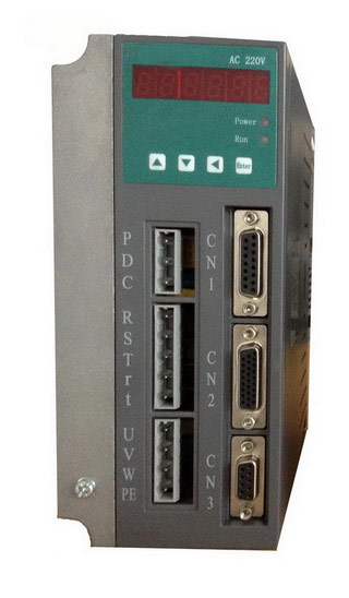 Gozuk synchronous ac servo drive is designed and manufactured, employing the advanced control algorithm based on the market demand, which can realize ...
A BLDC motor may have a trapezoidal Back EMF, there is something called Trapezoidal Motor Control Methodalogy (TRZ). TRZ is an extension of 6-step control ...
Permanent Magnet motors are more efficient than SCIM as the field in the rotor is permanently there. The big advantage for permanent magnet motors is in ...
Gozuk synchronous ac servo drive is designed and manufactured, employing the advanced control algorithm based on the market demand, which can realize ...
A BLDC motor may have a trapezoidal Back EMF, there is something called Trapezoidal Motor Control Methodalogy (TRZ). TRZ is an extension of 6-step control ...
Permanent Magnet motors are more efficient than SCIM as the field in the rotor is permanently there. The big advantage for permanent magnet motors is in ...