FAQ
BLDC was coined as when using the standard "six step" energisation it really is very similar to the action carried out by the commutator in a brushed motor. The motor is of course an AC motor but in terms of the BEMF waveform shape it MAY (underlined!!) have been designed with a more trapezoidal BEMF which CAN (underlined!!) give a smoother torque compared with a sine BEMF and six step energisation.
The current through the windings can be anything you want. Preferably you are driving a synchronous motor (that is NOT BLDC) with a sinusoidal current to get a sinusoidal voltage across the windings, what the synchronous motor is designed for. The current through the BLDC motor usually has the form of a "modified" square wave. The current through each winding is either steady positive, zero or steady negative. It is during the zero period you read the BEMF from that winding to establish the rotor location for a sensorless BLDC so you (that is the controller) can switch the current through the windings at the right time.
The current through the windings can be anything you want. Preferably you are driving a synchronous motor (that is NOT BLDC) with a sinusoidal current to get a sinusoidal voltage across the windings, what the synchronous motor is designed for. The current through the BLDC motor usually has the form of a "modified" square wave. The current through each winding is either steady positive, zero or steady negative. It is during the zero period you read the BEMF from that winding to establish the rotor location for a sensorless BLDC so you (that is the controller) can switch the current through the windings at the right time.
A BLDC motor may have a trapezoidal Back EMF, there is something called Trapezoidal Motor Control Methodalogy (TRZ). TRZ is an extension of 6-step control with additional switching states generated to allow winding current to ramp up/down in each phase prior to/after each commutation instant. Trapezoidal motor winding currents, achieve a low noise performance.
Brushless DC motors are generally, although not always, three phase devices. They are wired in either a Y (Wye, Star, T) or Δ (Delta) configuration, but in either case there are three connecting wires, and the current input to any two coils must be output through the third. That is,
C = –(A + B) where A, B, and C are the current flowing through each leg of the 3-phase brushless motor.
In theory, it is possible to control the rotor flux vector in any n-phase machine. People play with five and six phase machines all the time but the single phase machine seems to be the singularity because of the bidirectional air gap flux. I think mathematically we can work out some way of controlling that flux but as others have said here, why bother?
One more assumption that I see is that the single phase machine is incapable of higher powers. The single phase machine can be designed to very high powers, but we don't do it because the machines would be much larger than a 3 phase machine and take up more material. In fact there are relatively large single phase machines in the integral power range, designed mainly for rural use, where three phase power is not available.
Capacitor start single phase motors have a stationary switch & centrifugal switch that switch the motor out of the start winding to the run winding. The centrifugal switch requires the rotor to turn at a certain speed (apprx. 3/4 speed) to engage the contacts on the stationary switch. Its possible the motor would never get out of the start winding and quickly fry.
I did some analysis on an induction motor some years ago re speed or torque control at low speed without a sensor. I concluded that there was nothing to sense and that it could not be done. In the last twenty years I have seen some improvement in sensorless control, but have not seen anyone do it at zero speed. I build motion bases using induction motors as servo motors, and I do get full torque at stall with a V/f drive using a feedback pot for position control.
What happens at the manufacturer is that the specification for equipment is written (by the end user, or some hired intermediary) around some operating point ... and most often, that point is the "full load" or "100 percent" rating of the machine. Therefore, the design effort goes into making that specified operating point the best possible in a variety of terms, including: optimizing material usage during manufacture, minimizing material and labor costs during manufacture, optimizing the spectrum of performance criteria (including efficiency at the specified operating point), maximizing overall equipment reliability, minimizing personnel hazards during manufacture and operation, and maximizing accessibility for maintenance purposes. Sometimes one choice benefits more than one result ... but far more often, there is a trade off between the benefits and some determination is made on what is most "important". And as we are all different human beings, so too does the heirarchy change from one consumer to the next.
The difficulty - as you've already noted - arises when the SPECIFIED performance requirement (i.e. full load) is not the same as the ACTUAL performance requirement.
The difficulty - as you've already noted - arises when the SPECIFIED performance requirement (i.e. full load) is not the same as the ACTUAL performance requirement.
There are 100% electric cars being made or regular cars modified into servo motors by many companies. Range is the issue. Some claim to 200 mile range - not sure if that is real or not as my modified to 100% electric Chevy Equinox by Amp Electric has a range of 60-85 miles from its 37kwh Lion battery pack depending on how radical acceleration. If I stay below what most folks do (5ft/sec2) or if I enjoy my corvette like starts (10-15ft/sec2). Although efficiency is very similar for fast or slow acceleration, the batteries unfortunately discharge faster with high current demand. Until these electric car companies begin incorporating proper usage of super caps this will continue to be an issue. Any AS or PM motor design will do. Mine is 2 pc 350v PMDC frameless Delphi motors for about 160kw max output and base speed of about 2500rpm to 9000rpm max with field weakening & resolver feedback thru approx 8:1 planetary gearboxes.
 Servo Motor & Drives
Category
Featured
 Assuming that you checked the mechanical properties and the centrifugal force at the rotor at the higher speed from 50Hz to 60Hz, and they are OK, then ...
The troubleshooting guide outlines a comprehensive variety of motor problems. Generally the categories are arranged according to symptoms offering brief ...
The main difference between AC and DC motors is that the magnetic field generated by the stator rotates in the case of AC motors. A rotating magnetic ...
 First, 7 things to consider when choosing an electric motor: Choosing the right motor isn’t always straightforward. There are so many variables to ...
Induction motors operate on the principal of current induction in the rotor which must rotate at a speed less than synchronous speed for induction to ...
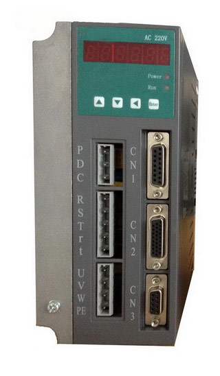
 Gozuk synchronous ac servo drive is designed and manufactured, employing the advanced control algorithm based on the market demand, which can realize ...
A BLDC motor may have a trapezoidal Back EMF, there is something called Trapezoidal Motor Control Methodalogy (TRZ). TRZ is an extension of 6-step control ...
Permanent Magnet motors are more efficient than SCIM as the field in the rotor is permanently there. The big advantage for permanent magnet motors is in ...
