Electric Motor Testing Tips
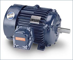
Electric motors are usually a tough lot. They operate in a variety of environments, indoor and out. Despite the best design, proper setup, and regular maintenance, they still can fail. Testing motors regularly should create an idea of the motor's health and a general feeling of when it may fail.
A collection of really good tips from PdMA Corporation, an industry leader in the field of predictive maintenance (PdM) and condition monitoring in the field of Electric Motor Testing.
Motor Failed…Who Cares?
Too often we hear maintenance & reliability experts downplay the data analysis or testing of motors that have failed from a stator fault. "Why would you need test equipment to test a stator fault?" we might hear. The mistake these "experts" make is to assume that troubleshooting a motor begins with failure analysis. Smart motors are on the market, but we haven't seen any with a big red flag that pops up with the words "STATOR FAULT" when it trips or fails to start. The reality most non-clairvoyant technicians face is they don't know exactly what failed, or if anything failed at all. Is it the motor, the load, the starter or maybe a nuisance trip? Remember a very important role of your predictive technologies is to assist the technicians in a quick recovery effort of production in the unfortunate situation of an unplanned outage. Performing some quick tests such as phase resistance, phase inductance, and ground wall tests can allow the technician to isolate quickly focus on or off of the electric motor and hasten good decision-making in deciding if a repair or replacement is necessary. A simple phase imbalance test may just prevent you from replacing a motor that doesn't need to be replaced.
It's Not Always the Motor's Fault
When testing a motor it is good practice to thoroughly test the entire motor circuit. A Wound Rotor Motor has two circuits – the stator circuit, which is very similar to a standard AC induction motor, and a rotor circuit. The rotor circuit usually consists of rotor windings, rings and brushes, and a resistor bank controlled using contactors. Depending on the application, the rotor circuit is used to control the torque, speed, or startup current of the motor. The external portion of the rotor circuit usually consists of an external resistor bank with a number of resistance steps. An unbalance of resistance in the resistor bank will cause an unbalance of the flux in the rotor creating a situation similar to a broken rotor bar. There are several tests using the MCEMAX that can be performed to evaluate this situation. With the motor de-energized, a standard test can be performed on each step of the resistor bank circuit to ensure resistance is balanced through each step and when the resistor bank is fully shorted out. With the motor running, a rotor evaluation test can be performed to look for a current unbalance during startup and after the motor is at full speed. An In-Rush test can be used to evaluate startup and switching times when troubleshooting anomalies in the rotor circuit.
The Hidden Sensor
The electric motor can be utilized like a complex sensor installed on a system to monitor the health and reliability of the entire system. Not just electrical, but mechanical anomalies will be transferred through the machine train to the rotor, across the air gap, and into the stator. From the stator, current analysis can be utilized to record the quantitative and qualitative data for baseline and trend analysis.
How Do I Test Large DC Armature Leads?
As DC motors get larger, the circular mils of cable supplying the armature circuit can grow to a size that does not fit in the standard AC/DC current probe. In many cases, you have multiple cables attached to a bus bar supplying power to the DC armature and a single DC probe does not exist (that we are aware of) to encompass this type of configuration. Before you throw up the white flag and opt to not perform a current capture, consider the flexible Rogowski Coil. As long as the supply to the armature is from a DC drive, which is a rectified DC signal, the Rogowski Coil will be able to provide a qualitative analysis of the acquired DC signal. The minimum frequency response of a Rogowski Coil may be 5-10Hz. The normal full wave rectified DC signal will carry a ripple frequency of 360Hz. This is more than enough variation in current for the Rogowski Coil to acquire a clear indication of the output performance of the DC drive as well as the performance of the DC motor.
<- - Make a Comment - ->
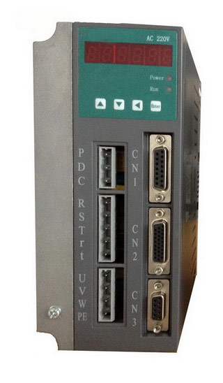
 Servo Motor & Drives