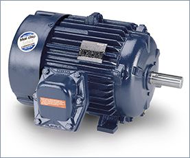
Frequency inverter
Assuming that you checked the mechanical properties and the centrifugal force at the rotor at the higher speed from 50Hz to 60Hz,  and they are OK, then you have to consider that the flux in the machine will go down by the ratio of the increase of frequency to 60Hz. Also the inductances will increase, so locked amps will be down, Locked rotor torque will be down, power factor will change, and efficiency will change. No load amps will decrease. If you want to change the electrical design to make it like it was for 50Hz then you have to increase the number of turns of the motor, but you have to know what you are doing.
Please note that except the change in the asynchronous speed of the motor machine, many other parameters will change. This will include the effective phase impedance of the motor, the current/voltage levels, etc. Also, please note that the torque-speed curve and the associated efficiencies will be affected by the change in frequency 60Hz to 50Hz.
and they are OK, then you have to consider that the flux in the machine will go down by the ratio of the increase of frequency to 60Hz. Also the inductances will increase, so locked amps will be down, Locked rotor torque will be down, power factor will change, and efficiency will change. No load amps will decrease. If you want to change the electrical design to make it like it was for 50Hz then you have to increase the number of turns of the motor, but you have to know what you are doing.Please note that except the change in the asynchronous speed of the motor machine, many other parameters will change. This will include the effective phase impedance of the motor, the current/voltage levels, etc. Also, please note that the torque-speed curve and the associated efficiencies will be affected by the change in frequency 60Hz to 50Hz.
Inverter duty and vector duty describe a class of AC induction motors that are specifically designed for use with frequency inverter. The high switching frequencies and fast voltage rise times of frequency inverters can produce high voltage peaks in the windings of standard AC motors that exceed their insulation break down voltage. Also, operating motors for an extended time at low motor rpm reduces the flow of cooling air, which results in an increase in temperature. NEMA-rated inverter- or vector-duty motors use high-temperature insulating materials that can withstand higher voltage spikes and operating temperatures. This reduces the stress on the insulation system.
Frequency inverter variable loads such as pumps, hydraulic systems, and fans. In these applications, motor efficiency is often poor due to operation at low loads and can be improved by using a frequency inverter in place of speed controllers such as belts and pulleys, throttle valves, fan dampers, and magnetic clutches. E.g., a pump or fan, controlled by a frequency inverter, running at half-speed consumes only one-eighth of the energy com pared to one running at full speed, resulting in consider able energy savings.
Frequency inverter variable loads such as pumps, hydraulic systems, and fans. In these applications, motor efficiency is often poor due to operation at low loads and can be improved by using a frequency inverter in place of speed controllers such as belts and pulleys, throttle valves, fan dampers, and magnetic clutches. E.g., a pump or fan, controlled by a frequency inverter, running at half-speed consumes only one-eighth of the energy com pared to one running at full speed, resulting in consider able energy savings.
Motors are commonly killed by one of two things: insulation failure or bearing failure. The dramatically simplified cause of these failures is heat and/or excessive voltage. The question is: How does use of a frequency inverter contribute to these failure modes, and how can these contributing factors be mitigated?
Motors are not 100 percent efficient, and require cooling. TEFC motors are cooled by a shaft-mounted fan. If a particular load application has a relatively high turndown ratio resulting in a very slow shaft speed, the cooling from the fan may be adversely affected. It cannot be assumed that a motor will accommodate an infinite turndown ratio without overheating its insulation system. Remember the "10 degree" rule of thumb discussed earlier. Motor manufacturers have recommended operation speed ranges for their motors. Operation restrictions on the turndown of the equipment connected to the motor should reflect these operation speed range recommendations.
As stated earlier, IGBTs can switch on and off extremely fast. The speed with which they can switch from 0 V to full dc bus voltage is referred to as rise time, or dv/dt. There is a phenomenon called "reflected wave" that is exacerbated by the IGBT's characteristic fast rise time (around 0.1 microseconds). The situation occurs when there is a mismatch between the interconnecting cable impedance and the motor. The motor terminals reflect the voltage rise back on the cable. This reflection on longer cable lengths can reinforce subsequence pulses, resulting in increasing electrical resonance as the carrier frequency is increased. This reflected wave can result in a voltage transient up to two times the dc bus voltage. Again, this dc bus voltage can be 1.414 times the ac input voltage. In a 480 V system, this can result in transients in excess of 1200 V. Faster rise times reduce the cable length at which this phenomenon is experienced. One manufacturer's general rule of thumb is that this can become an issue if cable length between the frequency inverter and motor exceeds 15 ft. In real-world applications, having this short of a length is pretty ambitious. Other manufacturers have recommendations for the maximum acceptable carrier frequency. Another recommended solution is to provide filtering devices between the frequency inverter and motor to mitigate the voltage overshoot, but that also adds cost and complexity.
 Servo Motor & Drives
Category
Featured
Assuming that you checked the mechanical properties and the centrifugal force at the rotor at the higher speed from 50Hz to 60Hz, and they are OK, then ...
The troubleshooting guide outlines a comprehensive variety of motor problems. Generally the categories are arranged according to symptoms offering brief ...
The main difference between AC and DC motors is that the magnetic field generated by the stator rotates in the case of AC motors. A rotating magnetic ...
 First, 7 things to consider when choosing an electric motor: Choosing the right motor isn’t always straightforward. There are so many variables to ...
Induction motors operate on the principal of current induction in the rotor which must rotate at a speed less than synchronous speed for induction to ...
First, 7 things to consider when choosing an electric motor: Choosing the right motor isn’t always straightforward. There are so many variables to ...
Induction motors operate on the principal of current induction in the rotor which must rotate at a speed less than synchronous speed for induction to ...
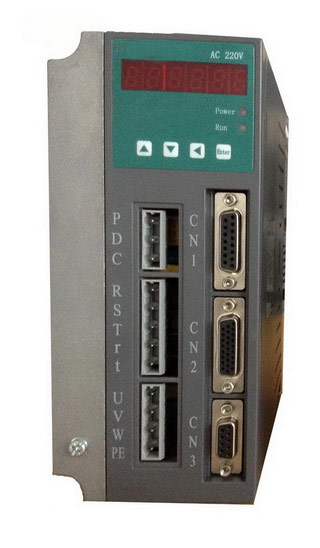 Gozuk synchronous ac servo drive is designed and manufactured, employing the advanced control algorithm based on the market demand, which can realize ...
A BLDC motor may have a trapezoidal Back EMF, there is something called Trapezoidal Motor Control Methodalogy (TRZ). TRZ is an extension of 6-step control ...
Permanent Magnet motors are more efficient than SCIM as the field in the rotor is permanently there. The big advantage for permanent magnet motors is in ...
Gozuk synchronous ac servo drive is designed and manufactured, employing the advanced control algorithm based on the market demand, which can realize ...
A BLDC motor may have a trapezoidal Back EMF, there is something called Trapezoidal Motor Control Methodalogy (TRZ). TRZ is an extension of 6-step control ...
Permanent Magnet motors are more efficient than SCIM as the field in the rotor is permanently there. The big advantage for permanent magnet motors is in ...