Wiki
Voltage spikes do not usually present a problem in 220V AC drive applications. The reason this is true is that all NEMA standard motors use an insulation that is designed to operate at 600V continuously and withstand intermittent voltage spikes of 1000V (a new motor can often withstand spikes to 1200V). Even if a spike were three times normal peak voltage (325V), it would still be within the 1000V limit. The net result is that standard motors are well suited for operation in 220V AC drive applications as long as the AC drive and motor manufacturer's cable length guidelines are followed. Always consult the manufacturer if the cable between the AC drive and motor will exceed 200 feet. If higher than normal ambient temperatures exist, you may want to upgrade to a motor that uses Class F insulation but, "special" inverter duty insulation is not required.
Unfortunately this is not always the case for 380V applications. Due to the high peak voltage (650V), even relatively small spikes can exceed the 1000V limit of standard motors. If the cable length between the AC drive and a standard motor exceeds 25 feet, a load reactor or dv/dt filter is always recommended. Always follow the manufacturers cable length guidelines closely when using standard motors in 380V AC drive applications.
Unfortunately this is not always the case for 380V applications. Due to the high peak voltage (650V), even relatively small spikes can exceed the 1000V limit of standard motors. If the cable length between the AC drive and a standard motor exceeds 25 feet, a load reactor or dv/dt filter is always recommended. Always follow the manufacturers cable length guidelines closely when using standard motors in 380V AC drive applications.
CO2 is probably the best alternative if an Oily winding has to be cleaned on site but is it not 100% and it is not straight forward. You should make your customer aware of all the facts. CO2 is a wonderful cleaning alternative. We have 6 CO2 machines and we use CO2 on a regular basis to clean windings and it is very effective in most cases. The one area where it is not very effective is with oil. It is very difficult to remove oil from a winding using CO2. It can be done but is a much slower process than other types of contamination because it does not fall in the way that most contaminant do. It will move along the surface but it will not fall off. You move it along to a gathering point where you can wipe it off. Imagine a patch of oil on the floor. You could use CO2 to clean that oil patch from the floor and that part of the floor will become clean, but the oil will be on another section of the floor. CO2 tends to move the oil around but never remove it 100%. And remember, if you can't point the nozzle at it, you will not remove it.
I have worked a great deal designing PM synchronous servo motors and their systems. Generally I work with precisions of 20 micron or less, this application is only about 800 micron of positioning accuracy. Following are some of the principles that I use to guide me through applications that might help you.
First- Accuracy is a function of the system not just the motor. The motor is merely a device for converting current into torque or force. Your system is comprised of the following: The Load, this is the mechanical portion of the system including the work and cutters; stiffer is always better when it comes to precision and if your load is too flexible the required precision could be impossible. The Controller/Amplifier this is where the servo loop is closed, system tuning parameters are set and the current is regulated to the motor windings, it is best to speak with a manufacture representative to ensure that you have to correct control for you application as this can be a complex subject. The Encoder or feed-back device, higher resolution is always better; I find I need a minimum of 10x resolution to my desired system accuracy. Finally the Motor, in positioning application I generally find lower inertia is better for accuracy, but in velocity control (which sounds more like what you need) I find higher inertia to be better for accuracy; this is because velocity control applications tend not to need high accelerations or rapid changes in speed, this means high inertia is your friend, it tends to smooth things out and help maintain a constant speed.
First- Accuracy is a function of the system not just the motor. The motor is merely a device for converting current into torque or force. Your system is comprised of the following: The Load, this is the mechanical portion of the system including the work and cutters; stiffer is always better when it comes to precision and if your load is too flexible the required precision could be impossible. The Controller/Amplifier this is where the servo loop is closed, system tuning parameters are set and the current is regulated to the motor windings, it is best to speak with a manufacture representative to ensure that you have to correct control for you application as this can be a complex subject. The Encoder or feed-back device, higher resolution is always better; I find I need a minimum of 10x resolution to my desired system accuracy. Finally the Motor, in positioning application I generally find lower inertia is better for accuracy, but in velocity control (which sounds more like what you need) I find higher inertia to be better for accuracy; this is because velocity control applications tend not to need high accelerations or rapid changes in speed, this means high inertia is your friend, it tends to smooth things out and help maintain a constant speed.
The troubleshooting guide outlines a comprehensive variety of motor problems. Generally the categories are arranged according to symptoms offering brief suggestions concerning what to look for when investigating motor failures (why motor fails?) and often providing advice on how to correct the problem once it has been identified.
Motor Shuts Off Before Full Speed
A. Motor also hums (single phase motor)
Run winding may have a loose connection - disassemble motor in order to make the appropriate repair
C. Excessively low voltage.
F. Bad capacitor Run winding is burned out - motor must be replaced or rewound
B. Overloaded
Reduce the load. A reasonable overload or voltage drop of 10-15% will reduce speed only 1 to2 percent.
A report of any greater drop would be questionable.
D. Inaccurate method of measuring RPM
Check meter using another device or method.
E. Wrong connections
Motor Shuts Off Before Full Speed
A. Motor also hums (single phase motor)
F. Bad capacitor
B. Overloaded
D. Inaccurate method of measuring RPM
E. Wrong connections
Some motors are designed to operate at two, three, or four separate designated speeds. The speed of an induction motor depends on the number of poles built into the motor and the frequency of the electrical power supply. Multi-speed motors are available up to 500 hp, and are very reliable, but have several drawbacks.
The stator slots have to be bigger than those of single-speed motors in order to accommodate two or more sets of windings. As a result, the motors are bulkier and cannot be easily retrofitted. The current-carrying capacity of the copper is poorly utilized since only one set of windings is active at a time. Because of their dual speed design, however, they still have lower operating efficiencies than comparably sized single speed motors.
Multiple speed motor starters typically cost up to twice as much as single-speed motor starters. Multi-speed motors themselves cost 50-100 percent more than single-speed motors. Two-speed motors can be used to save energy in such applications as air volume control in facilities that have large differences in day-to-night or weekday-to-weekend air flow requirements. A dual speed fan rated for 1,200 and 1,800 rpm, for instance, can reduce fan energy requirements at night and on weekends by 70 percent.
Inverter duty and vector duty describe a class of AC induction motors that are specifically designed for use with frequency inverter. The high switching frequencies and fast voltage rise times of frequency inverters can produce high voltage peaks in the windings of standard AC motors that exceed their insulation break down voltage. Also, operating motors for an extended time at low motor rpm reduces the flow of cooling air, which results in an increase in temperature. NEMA-rated inverter- or vector-duty motors use high-temperature insulating materials that can withstand higher voltage spikes and operating temperatures. This reduces the stress on the insulation system.
Frequency inverter variable loads such as pumps, hydraulic systems, and fans. In these applications, motor efficiency is often poor due to operation at low loads and can be improved by using a frequency inverter in place of speed controllers such as belts and pulleys, throttle valves, fan dampers, and magnetic clutches. E.g., a pump or fan, controlled by a frequency inverter, running at half-speed consumes only one-eighth of the energy com pared to one running at full speed, resulting in consider able energy savings.
Frequency inverter variable loads such as pumps, hydraulic systems, and fans. In these applications, motor efficiency is often poor due to operation at low loads and can be improved by using a frequency inverter in place of speed controllers such as belts and pulleys, throttle valves, fan dampers, and magnetic clutches. E.g., a pump or fan, controlled by a frequency inverter, running at half-speed consumes only one-eighth of the energy com pared to one running at full speed, resulting in consider able energy savings.
Unlike other types of single-phase motors, shaded-pole motors have only one main winding and no start winding or switch. As in other induction motors, the rotating part is a squirrel-cage rotor. Starting is by means of a design that uses a continuous copper loop around a small portion of each motor pole. Currents in this copper loop delay the phase of magnetic flux in that part of the pole enough to provide a rotating field. This rotating field effect produces a very low starting torque compared to other classes of single-phase motors. Although direction of rotation is not normally reversible, some shaded-pole motors are wound with two main windings that reverse the direction of the field. Slip in the shaded-pole motor is not a problem, as the current in the stator is not controlled by a counter-voltage determined by rotor speed, as in other types of single-phase motors. Speed can therefore be controlled merely by varying voltage, or through a multitap winding.
Shaded-pole motors are best suited to low-power household application, because the motors have low starting torque and efficiency ratings. Because of the weak starting torque, shaded-pole motors are built only in small sizes ranging from 1/20 to 1/6 hp. Applications for this type of motor include fans, can openers, blowers, and electric razors.
Shaded-pole motors are best suited to low-power household application, because the motors have low starting torque and efficiency ratings. Because of the weak starting torque, shaded-pole motors are built only in small sizes ranging from 1/20 to 1/6 hp. Applications for this type of motor include fans, can openers, blowers, and electric razors.
The capacitor-start motor is a modified split-phase motor. A capacitor connected in series with the starting winding creates a phase shift of approximately 80 degrees between the starting and running winding. This is substantially higher than the 45 degrees of a split-phase motor and results in a higher starting torque. Capacitor-start motors provide more than double the starting torque with one-third less starting cur rent than the split-phase motor. Like the split-phase motor, the capacitor start motor also has a starting mechanism, either a mechanical centrifugal switch or solid-state electronic switch. This disconnects not only the start winding, but also the capacitor when the motor reaches about 79% of rated speed.
The capacitor-start motor is more expensive than a comparable split-phase design because of the additional cost of the start capacitor. However, the application range is much wider because of higher starting torque and lower starting current. The job of the capacitor is to improve the starting torque and not the power factor, as it's only in the circuit for a few seconds at the instant of starting. The capacitor can be a source of trouble if it becomes short circuited or open-circuited. A short-circuited capacitor will cause an excessive amount of current to flow through the staring winding, while an open capacitor will cause the motor to not start.
The capacitor-start motor is more expensive than a comparable split-phase design because of the additional cost of the start capacitor. However, the application range is much wider because of higher starting torque and lower starting current. The job of the capacitor is to improve the starting torque and not the power factor, as it's only in the circuit for a few seconds at the instant of starting. The capacitor can be a source of trouble if it becomes short circuited or open-circuited. A short-circuited capacitor will cause an excessive amount of current to flow through the staring winding, while an open capacitor will cause the motor to not start.
A single-phase split-phase induction motor uses a squirrel-cage rotor that is identical to that in a three phase motor. To produce a rotating magnetic field, the single-phase current is split by two windings, the main running winding and an auxiliary starting winding, which is displaced in the stator 90 electrical degrees from the running winding. The starting winding is connected in series with a switch, centrifugally or electrically operated, to disconnect it when the starting speed reaches about 75 % of full-load speed.
Phase displacement is accomplished by the difference in inductive reactance of the start and run windings as well as the physical displacement of the windings in the stator. The starting winding is wound on the top of the stator slots with fewer turns of smaller-diameter wire. The running winding has many turns of large-diameter wire wound in the bottom of the stator slots that give it a higher inductive reactance than the starting winding.
Phase displacement is accomplished by the difference in inductive reactance of the start and run windings as well as the physical displacement of the windings in the stator. The starting winding is wound on the top of the stator slots with fewer turns of smaller-diameter wire. The running winding has many turns of large-diameter wire wound in the bottom of the stator slots that give it a higher inductive reactance than the starting winding.
Most home and business appliances operate on single phase AC power. For this reason, single-phase AC motors are in widespread use. A single-phase induction motor is larger in size, for the same horsepower, than a three-phase motor. When running, the torque produced by a single phase motor is pulsating and irregular, contributing to a much lower power factor and efficiency than that of a polyphase motor. Single-phase AC motors are generally available in the fractional to 10-hp range and all use a solid squirrel-cage rotor.
The single-phase induction motor operates on the principle of induction, just as does a three-phase motor. Unlike three phase motors, they are not self-starting. Whereas a three-phase induction motor sets up a rotating field that can start the motor, a single-phase motor needs an auxiliary means of starting. Once a single-phase induction motor is running, it develops a rotating magnetic field.
The single-phase induction motor operates on the principle of induction, just as does a three-phase motor. Unlike three phase motors, they are not self-starting. Whereas a three-phase induction motor sets up a rotating field that can start the motor, a single-phase motor needs an auxiliary means of starting. Once a single-phase induction motor is running, it develops a rotating magnetic field.
The three-phase synchronous motor is a unique and specialized motor. As the name suggests, this motor runs at a constant speed from no load to full load in synchronism with line frequency. As in squirrel-cage induction motors, the speed of a synchronous motor is determined by the number of pairs of poles and the line frequency.
The operation of a typical three-phase synchronous motor can be summarized as follows:
The operation of a typical three-phase synchronous motor can be summarized as follows:
- Three-phase AC voltage is applied to the stator windings and a rotating magnetic field is produced.
- DC voltage is applied to the rotor winding and a second magnetic field is produced.
- The rotor then acts like a magnet and is attracted by the rotating stator field.
- This attraction exerts a torque on the rotor and causes it to rotate at the synchronous speed of the rotating stator field.
- The rotor does not require the magnetic induction from the stator field for its excitation. As a result, the motor has zero slip compared to the induction motor, which requires slip in order to produce torque.
The wound-rotor induction motor (sometimes called a slip-ring motor) is a variation on the standard cage induction motors. Wound-rotor motors have a three-phase winding wound on the rotor, which is terminated to slip rings. The operation of the motor can be summarized as follows.
- The rotor slip rings connect to start-up resistors in order to provide current and speed control on start-up.
- When the motor is started, the frequency of current flowing through the rotor windings is nearly 60 Hz.
- Once up to full speed, the rotor current frequency drops down below 10 Hz to nearly a DC signal.
- The motor is normally started with full external resistance in the rotor circuit that is gradually reduced to zero, either manually or automatically.
- This results in a very high starting torque from zero speed to full speed at a relatively low starting current.
- With zero external resistance, the wound-rotor motor characteristics approach those of the squirrel cage motor.
- Interchanging any two stator voltage supply leads reverses the direction of rotation.
 Servo Motor & Drives
Category
Featured
 Assuming that you checked the mechanical properties and the centrifugal force at the rotor at the higher speed from 50Hz to 60Hz, and they are OK, then ...
The troubleshooting guide outlines a comprehensive variety of motor problems. Generally the categories are arranged according to symptoms offering brief ...
The main difference between AC and DC motors is that the magnetic field generated by the stator rotates in the case of AC motors. A rotating magnetic ...
Assuming that you checked the mechanical properties and the centrifugal force at the rotor at the higher speed from 50Hz to 60Hz, and they are OK, then ...
The troubleshooting guide outlines a comprehensive variety of motor problems. Generally the categories are arranged according to symptoms offering brief ...
The main difference between AC and DC motors is that the magnetic field generated by the stator rotates in the case of AC motors. A rotating magnetic ...
 First, 7 things to consider when choosing an electric motor: Choosing the right motor isn’t always straightforward. There are so many variables to ...
Induction motors operate on the principal of current induction in the rotor which must rotate at a speed less than synchronous speed for induction to ...
First, 7 things to consider when choosing an electric motor: Choosing the right motor isn’t always straightforward. There are so many variables to ...
Induction motors operate on the principal of current induction in the rotor which must rotate at a speed less than synchronous speed for induction to ...
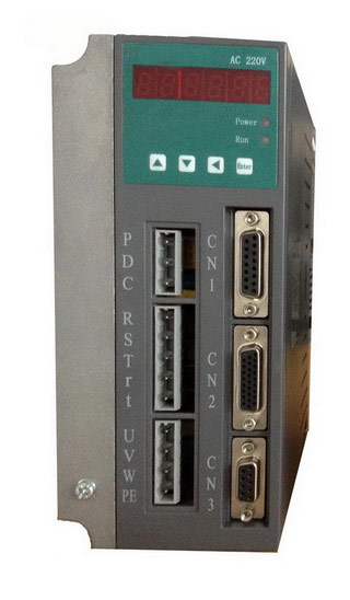 Gozuk synchronous ac servo drive is designed and manufactured, employing the advanced control algorithm based on the market demand, which can realize ...
A BLDC motor may have a trapezoidal Back EMF, there is something called Trapezoidal Motor Control Methodalogy (TRZ). TRZ is an extension of 6-step control ...
Permanent Magnet motors are more efficient than SCIM as the field in the rotor is permanently there. The big advantage for permanent magnet motors is in ...
Gozuk synchronous ac servo drive is designed and manufactured, employing the advanced control algorithm based on the market demand, which can realize ...
A BLDC motor may have a trapezoidal Back EMF, there is something called Trapezoidal Motor Control Methodalogy (TRZ). TRZ is an extension of 6-step control ...
Permanent Magnet motors are more efficient than SCIM as the field in the rotor is permanently there. The big advantage for permanent magnet motors is in ...