Motor control
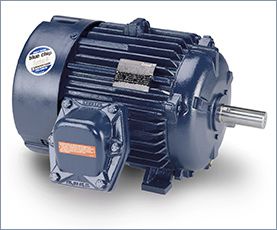
I'm in a motor design. Currently, I'm using JMAG Express to estimate the right sizing requirements for a 3-phase Induction Motor that I want to build among friends. As you can see from the picture, I need to be able to reach 3200 RPMs speed, 440 N*m torque and 120kW of max power. I've played around with some of the values in JMAG to reach a weight of around 20kg as you can see from the picture. The low weight is a very important requirement for the project and it should not exceed 50kg. I'm using 48 slots for the stator and 26 for the rotor which is a Caged type. Winding is concentrated with 32 turns.

Assuming that you checked the mechanical properties and the centrifugal force at the rotor at the higher speed from 50Hz to 60Hz,  and they are OK, then you have to consider that the flux in the machine will go down by the ratio of the increase of frequency to 60Hz. Also the inductances will increase, so locked amps will be down, Locked rotor torque will be down, power factor will change, and efficiency will change. No load amps will decrease. If you want to change the electrical design to make it like it was for 50Hz then you have to increase the number of turns of the motor, but you have to know what you are doing.
Please note that except the change in the asynchronous speed of the motor machine, many other parameters will change. This will include the effective phase impedance of the motor, the current/voltage levels, etc. Also, please note that the torque-speed curve and the associated efficiencies will be affected by the change in frequency 60Hz to 50Hz.
and they are OK, then you have to consider that the flux in the machine will go down by the ratio of the increase of frequency to 60Hz. Also the inductances will increase, so locked amps will be down, Locked rotor torque will be down, power factor will change, and efficiency will change. No load amps will decrease. If you want to change the electrical design to make it like it was for 50Hz then you have to increase the number of turns of the motor, but you have to know what you are doing.Please note that except the change in the asynchronous speed of the motor machine, many other parameters will change. This will include the effective phase impedance of the motor, the current/voltage levels, etc. Also, please note that the torque-speed curve and the associated efficiencies will be affected by the change in frequency 60Hz to 50Hz.
I used a NEMA-design induction motor, which have fairly high inductance so they can be line-started. I don't recall the inductances, but I made sure to use a motor with a similar power rating to the variable frequency drive.
Don't worry about the inductance without the rotor. If you work through the equations you'll find that the stator R-L time constant dominates the current ripple at the switching frequency. Not enough flux crosses the air-gap at the switching frequency to make much difference.
The rotor does modify the inductance. You will have to be a little careful about how much voltage you apply to the phases, because you can easily generate too much current (a given, since there's no back-emf, either). But at the switching frequency, very little flux crosses the airgap so the rotor does not really figure into the equations for DC bus ripple current. And in this sort of testing, it's DC bus ripple that can accidentally destroy the variable frequency drive you are trying to verify!
CO2 is probably the best alternative if an Oily winding has to be cleaned on site but is it not 100% and it is not straight forward. You should make your customer aware of all the facts. CO2 is a wonderful cleaning alternative. We have 6 CO2 machines and we use CO2 on a regular basis to clean windings and it is very effective in most cases. The one area where it is not very effective is with oil. It is very difficult to remove oil from a winding using CO2. It can be done but is a much slower process than other types of contamination because it does not fall in the way that most contaminant do. It will move along the surface but it will not fall off. You move it along to a gathering point where you can wipe it off. Imagine a patch of oil on the floor. You could use CO2 to clean that oil patch from the floor and that part of the floor will become clean, but the oil will be on another section of the floor. CO2 tends to move the oil around but never remove it 100%. And remember, if you can't point the nozzle at it, you will not remove it.
I have worked a great deal designing PM synchronous servo motors and their systems. Generally I work with precisions of 20 micron or less, this application is only about 800 micron of positioning accuracy. Following are some of the principles that I use to guide me through applications that might help you.
First- Accuracy is a function of the system not just the motor. The motor is merely a device for converting current into torque or force. Your system is comprised of the following: The Load, this is the mechanical portion of the system including the work and cutters; stiffer is always better when it comes to precision and if your load is too flexible the required precision could be impossible. The Controller/Amplifier this is where the servo loop is closed, system tuning parameters are set and the current is regulated to the motor windings, it is best to speak with a manufacture representative to ensure that you have to correct control for you application as this can be a complex subject. The Encoder or feed-back device, higher resolution is always better; I find I need a minimum of 10x resolution to my desired system accuracy. Finally the Motor, in positioning application I generally find lower inertia is better for accuracy, but in velocity control (which sounds more like what you need) I find higher inertia to be better for accuracy; this is because velocity control applications tend not to need high accelerations or rapid changes in speed, this means high inertia is your friend, it tends to smooth things out and help maintain a constant speed.
First- Accuracy is a function of the system not just the motor. The motor is merely a device for converting current into torque or force. Your system is comprised of the following: The Load, this is the mechanical portion of the system including the work and cutters; stiffer is always better when it comes to precision and if your load is too flexible the required precision could be impossible. The Controller/Amplifier this is where the servo loop is closed, system tuning parameters are set and the current is regulated to the motor windings, it is best to speak with a manufacture representative to ensure that you have to correct control for you application as this can be a complex subject. The Encoder or feed-back device, higher resolution is always better; I find I need a minimum of 10x resolution to my desired system accuracy. Finally the Motor, in positioning application I generally find lower inertia is better for accuracy, but in velocity control (which sounds more like what you need) I find higher inertia to be better for accuracy; this is because velocity control applications tend not to need high accelerations or rapid changes in speed, this means high inertia is your friend, it tends to smooth things out and help maintain a constant speed.
Some motors are designed to operate at two, three, or four separate designated speeds. The speed of an induction motor depends on the number of poles built into the motor and the frequency of the electrical power supply. Multi-speed motors are available up to 500 hp, and are very reliable, but have several drawbacks.
The stator slots have to be bigger than those of single-speed motors in order to accommodate two or more sets of windings. As a result, the motors are bulkier and cannot be easily retrofitted. The current-carrying capacity of the copper is poorly utilized since only one set of windings is active at a time. Because of their dual speed design, however, they still have lower operating efficiencies than comparably sized single speed motors.
Multiple speed motor starters typically cost up to twice as much as single-speed motor starters. Multi-speed motors themselves cost 50-100 percent more than single-speed motors. Two-speed motors can be used to save energy in such applications as air volume control in facilities that have large differences in day-to-night or weekday-to-weekend air flow requirements. A dual speed fan rated for 1,200 and 1,800 rpm, for instance, can reduce fan energy requirements at night and on weekends by 70 percent.
After replacing the pump motor controller for the second time, we decided to find out what caused the controller to burn up. After operating for several days, we noticed excessive motor current on the controller. While we had the pump down for inspection, the customer technician removed and cleaned the filter screen. To continue our test we started the pump and the motor current was back to normal. What we learned was as the clogged filter screen increased the back pressure on the pump. To maintain the correct flow (pump speed) caused an increase in motor current to overcome the increased backpressure from the clogged filter screen. The motor current feedback was not included in the system diagnostics and the operators had not indication of the impending failure. The systems integrator undertook two improvement actions. (1) Increase the frequency at which all filter screens received cleaning and maintenance and (2) Brought the motor current value into an alarm to warn (predictive) the operators when a drive controller motor current was approaching and unsafe value. Why did the system integrator perform this work? Driven by the customer, the contract was written to require the system integrator to support the system for a pre-determined period of time after the system acceptance test.
I was doing some tests the other day on slow speed control (1rpm). I thought that sinusoidal commutation and a high resolution encoder (4K CPT) would be "the thing" for controlling a multi-pole flat motor well (with detent torque - naming the EC90 flat from maxon). This would enable the controller to have better control during the commutation between coil switching. During the commutation the natural attraction of the rotor to the poles pulls and pushes the rotor into position. This is something that I thought sinusoidal commutation would help with. I was pleasantly surprised that using another controller that had just block commutation but a 53.5Khz current loop proved far superior in comparison to the 10KHz control on the sinusoidal drive!
It appears like many contributors treat this application as if it is a distribution board that is to be supplied by a 400m cable connection. That must be the reason why so many calls for a neutral, or earth return core, as well as for the very limited allowed voltage drop during start. In many applications we directly recommend reducing the terminal voltage during start, for a number of reasons, so why should it all of a sudden become detrimental in this situation? The motor has no way of knowing what has caused the reduced starting voltage anyway! As long as there is sufficient voltage to get the drive to start within a reasonable time, the start VD should cause no headache.
One important issue that has only been briefly touched upon by a single contributor is the economy: It should be our professional endeavour to make the total cost of ownership as low as possible, so it would be reasonable to include energy cost into the equation. The heavier cable as proposed by many, will obviously reduce the running losses considerably as compared to the smallest cable that will satisfy the technical requirements.
If this motor is intended to run for only brief periods each day, or maybe for only a few days or months, it will be bad economy to choose the heavy cable just because you can. Likewise, if this installation is part of a quotation, you could very well miss out on a much larger contract, because most clients will only look at the total sum, before addressing any technical issues.
Theoretically, Yes, if the conditions under which it's running are constant (on squirrel cage induction motors). In reality, it varies due to a variety of factors. These can include changes in load, input power, environmental conditions, etc. Speed control really has 2 effects - providing a wider range of speed capabilities with the same motor (adjustability) as well as smoothing out (or at least attempting to smooth out) the effects that would change the motor speed and transients in loading, input voltage, etc.
Practically, NO, for electric motors connected to the AC power line. The speed of an AC induction motor is a function of the AC frequency, the number of poles in the motor, and the load on the motor. Under no-load conditions, the speed is quite constant. Under load, the speed will vary since the motor torque comes from the lag in the phase current. Unless the motor runs slower than synchronous speed, it cannot produce the torque necessary to do its work. Synchronous motors run at constant speed.
Practically, NO, for electric motors connected to the AC power line. The speed of an AC induction motor is a function of the AC frequency, the number of poles in the motor, and the load on the motor. Under no-load conditions, the speed is quite constant. Under load, the speed will vary since the motor torque comes from the lag in the phase current. Unless the motor runs slower than synchronous speed, it cannot produce the torque necessary to do its work. Synchronous motors run at constant speed.
BLDC was coined as when using the standard "six step" energisation it really is very similar to the action carried out by the commutator in a brushed motor. The motor is of course an AC motor but in terms of the BEMF waveform shape it MAY (underlined!!) have been designed with a more trapezoidal BEMF which CAN (underlined!!) give a smoother torque compared with a sine BEMF and six step energisation.
The current through the windings can be anything you want. Preferably you are driving a synchronous motor (that is NOT BLDC) with a sinusoidal current to get a sinusoidal voltage across the windings, what the synchronous motor is designed for. The current through the BLDC motor usually has the form of a "modified" square wave. The current through each winding is either steady positive, zero or steady negative. It is during the zero period you read the BEMF from that winding to establish the rotor location for a sensorless BLDC so you (that is the controller) can switch the current through the windings at the right time.
The current through the windings can be anything you want. Preferably you are driving a synchronous motor (that is NOT BLDC) with a sinusoidal current to get a sinusoidal voltage across the windings, what the synchronous motor is designed for. The current through the BLDC motor usually has the form of a "modified" square wave. The current through each winding is either steady positive, zero or steady negative. It is during the zero period you read the BEMF from that winding to establish the rotor location for a sensorless BLDC so you (that is the controller) can switch the current through the windings at the right time.
A BLDC motor may have a trapezoidal Back EMF, there is something called Trapezoidal Motor Control Methodalogy (TRZ). TRZ is an extension of 6-step control with additional switching states generated to allow winding current to ramp up/down in each phase prior to/after each commutation instant. Trapezoidal motor winding currents, achieve a low noise performance.
Brushless DC motors are generally, although not always, three phase devices. They are wired in either a Y (Wye, Star, T) or Δ (Delta) configuration, but in either case there are three connecting wires, and the current input to any two coils must be output through the third. That is,
C = –(A + B) where A, B, and C are the current flowing through each leg of the 3-phase brushless motor.
 Servo Motor & Drives
Category
Featured
Assuming that you checked the mechanical properties and the centrifugal force at the rotor at the higher speed from 50Hz to 60Hz, and they are OK, then ...
The troubleshooting guide outlines a comprehensive variety of motor problems. Generally the categories are arranged according to symptoms offering brief ...
The main difference between AC and DC motors is that the magnetic field generated by the stator rotates in the case of AC motors. A rotating magnetic ...
 First, 7 things to consider when choosing an electric motor: Choosing the right motor isn’t always straightforward. There are so many variables to ...
Induction motors operate on the principal of current induction in the rotor which must rotate at a speed less than synchronous speed for induction to ...
First, 7 things to consider when choosing an electric motor: Choosing the right motor isn’t always straightforward. There are so many variables to ...
Induction motors operate on the principal of current induction in the rotor which must rotate at a speed less than synchronous speed for induction to ...
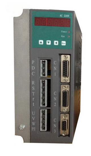 Gozuk synchronous ac servo drive is designed and manufactured, employing the advanced control algorithm based on the market demand, which can realize ...
A BLDC motor may have a trapezoidal Back EMF, there is something called Trapezoidal Motor Control Methodalogy (TRZ). TRZ is an extension of 6-step control ...
Permanent Magnet motors are more efficient than SCIM as the field in the rotor is permanently there. The big advantage for permanent magnet motors is in ...
Gozuk synchronous ac servo drive is designed and manufactured, employing the advanced control algorithm based on the market demand, which can realize ...
A BLDC motor may have a trapezoidal Back EMF, there is something called Trapezoidal Motor Control Methodalogy (TRZ). TRZ is an extension of 6-step control ...
Permanent Magnet motors are more efficient than SCIM as the field in the rotor is permanently there. The big advantage for permanent magnet motors is in ...