Synchronous motor
The three-phase synchronous motor is a unique and specialized motor. As the name suggests, this motor runs at a constant speed from no load to full load in synchronism with line frequency. As in squirrel-cage induction motors, the speed of a synchronous motor is determined by the number of pairs of poles and the line frequency.
The operation of a typical three-phase synchronous motor can be summarized as follows:
The operation of a typical three-phase synchronous motor can be summarized as follows:
- Three-phase AC voltage is applied to the stator windings and a rotating magnetic field is produced.
- DC voltage is applied to the rotor winding and a second magnetic field is produced.
- The rotor then acts like a magnet and is attracted by the rotating stator field.
- This attraction exerts a torque on the rotor and causes it to rotate at the synchronous speed of the rotating stator field.
- The rotor does not require the magnetic induction from the stator field for its excitation. As a result, the motor has zero slip compared to the induction motor, which requires slip in order to produce torque.
Synchronous motor technology has its roots in the electricity and magnetism experiments of Michael Faraday in 1830 and his discovery that a changing magnetic field can induce an electric current. Two years later Parisian instrument maker, Hippolyte Pixii, built the first alternator consisting of a revolving horseshoe magnet passing over two wound wire coils generating a simple form of alternating current (AC). During the late 19th century, the advantages of AC over the existing direct current (DC) technology espoused by Thomas Edison, led many inventors in the United States and Europe, such as Nikola Tesla, to advocate the development of AC motors.

A century later, synchronous AC motors still represent one of most widely used technologies. Simply put, a synchronous motor is a rotary motor in which the speed of the rotating part or shaft is in synchrony or spins in tandem with the line frequency oscillations of the supply current (typically 60 Hz in the US and 50 Hz in Europe and Asia). To accomplish this, synchronous motors contain electromagnets usually on the rotor and a winding of a coil of copper wire (aka the field coil) around the stator ring. A small space, or air gap, separates the stator from the rotor, allowing the rotor to spin freely when the supply current is turned on. Depending on design requirements, the location of the electromagnets or field coil are interchangeably mountable on the stator or the rotor. When excited, electromagnets and the field coil work together to create a magnetic field that rotates in time with the oscillations of the line current. The rotor locks in, or turns in step, with this field at the same rate causing the shaft to rotate quickly. Once this occurs, the motor reaches steady-state operation and is in synchrony or “in sync”. If the motor load increases beyond breakdown load, the motor falls out of sync, and the field winding no longer follows the rotating magnetic field.
Synchronous motors are available in low and high horsepower industrial sizes. In low-voltage applications, synchronous motors are in use where precise constant speed is required. Small synchronous motors are able to start without assistance if the moment of inertia of the rotor and its mechanical load is sufficiently small. Small synchronous motors are commonly used in line-powered electric clocks and appliance timers.
You can divide the synchronous machines in 2 groups, based on the principle they employ to generate torque:
- interaction of 2 independent fields, one generated on stator and the other on the rotor: let's call this group "excited" synchronous machines;
- the torque is generated by an anisotropic rotor structure and the presence of a magnetic field generated by the stator: the latter field will tend to attract the anisotropic rotor in order to minimize the reluctance of the path of the magnetic field itself; let's call this group "reluctance" machines.
Then, of course, you can also mix the 2 things, by providing an anisotropic structure with some way (see down) to independently excite a rotor field.
Now, 2 additions to the above: in the 1st group the excitation of the rotor field can be provided by both a field winding fed with current through slip-rings and brushes (the traditional power plant alternator) and then will call it "electrically excited" synchronous; or, excitation can be provided by permanent magnets placed somewhere in the rotor structure (either on the outer surface or inside), and then we'll call it "PM synchronous" machine.
Second precaution: though the physical principle is the same, *synchronous* reluctance machines are quite different from *switched* reluctance ones. The latter, in fact, have a salient structure also on the stator, the coils being supplied (a phase at a time) with DC current, that produces a magnetic field fixed in space: once the minimal reluctance position is achieved, the rotor would continue stay there (neglecting little oscillations) unless current is moved to a different phase. In *synchronous* reluctance, instead, the stator structure is more conventional, almost isotropic, and a set of AC currents is supplied to all the coils: this generates a rotating magnetic field, hence your "preferred position" is not reached and the rotor continues spinning.
 Servo Motor & Drives
Category
Featured
 Assuming that you checked the mechanical properties and the centrifugal force at the rotor at the higher speed from 50Hz to 60Hz, and they are OK, then ...
The troubleshooting guide outlines a comprehensive variety of motor problems. Generally the categories are arranged according to symptoms offering brief ...
The main difference between AC and DC motors is that the magnetic field generated by the stator rotates in the case of AC motors. A rotating magnetic ...
Assuming that you checked the mechanical properties and the centrifugal force at the rotor at the higher speed from 50Hz to 60Hz, and they are OK, then ...
The troubleshooting guide outlines a comprehensive variety of motor problems. Generally the categories are arranged according to symptoms offering brief ...
The main difference between AC and DC motors is that the magnetic field generated by the stator rotates in the case of AC motors. A rotating magnetic ...
 First, 7 things to consider when choosing an electric motor: Choosing the right motor isn’t always straightforward. There are so many variables to ...
Induction motors operate on the principal of current induction in the rotor which must rotate at a speed less than synchronous speed for induction to ...
First, 7 things to consider when choosing an electric motor: Choosing the right motor isn’t always straightforward. There are so many variables to ...
Induction motors operate on the principal of current induction in the rotor which must rotate at a speed less than synchronous speed for induction to ...
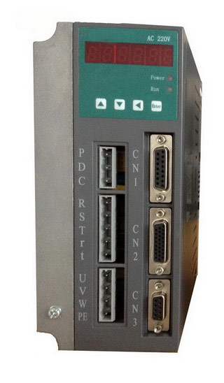 Gozuk synchronous ac servo drive is designed and manufactured, employing the advanced control algorithm based on the market demand, which can realize ...
A BLDC motor may have a trapezoidal Back EMF, there is something called Trapezoidal Motor Control Methodalogy (TRZ). TRZ is an extension of 6-step control ...
Permanent Magnet motors are more efficient than SCIM as the field in the rotor is permanently there. The big advantage for permanent magnet motors is in ...
Gozuk synchronous ac servo drive is designed and manufactured, employing the advanced control algorithm based on the market demand, which can realize ...
A BLDC motor may have a trapezoidal Back EMF, there is something called Trapezoidal Motor Control Methodalogy (TRZ). TRZ is an extension of 6-step control ...
Permanent Magnet motors are more efficient than SCIM as the field in the rotor is permanently there. The big advantage for permanent magnet motors is in ...