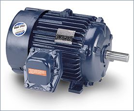
Induction motor
I'm in a motor design. Currently, I'm using JMAG Express to estimate the right sizing requirements for a 3-phase Induction Motor that I want to build among friends. As you can see from the picture, I need to be able to reach 3200 RPMs speed, 440 N*m torque and 120kW of max power. I've played around with some of the values in JMAG to reach a weight of around 20kg as you can see from the picture. The low weight is a very important requirement for the project and it should not exceed 50kg. I'm using 48 slots for the stator and 26 for the rotor which is a Caged type. Winding is concentrated with 32 turns.

Assuming that you checked the mechanical properties and the centrifugal force at the rotor at the higher speed from 50Hz to 60Hz,  and they are OK, then you have to consider that the flux in the machine will go down by the ratio of the increase of frequency to 60Hz. Also the inductances will increase, so locked amps will be down, Locked rotor torque will be down, power factor will change, and efficiency will change. No load amps will decrease. If you want to change the electrical design to make it like it was for 50Hz then you have to increase the number of turns of the motor, but you have to know what you are doing.
Please note that except the change in the asynchronous speed of the motor machine, many other parameters will change. This will include the effective phase impedance of the motor, the current/voltage levels, etc. Also, please note that the torque-speed curve and the associated efficiencies will be affected by the change in frequency 60Hz to 50Hz.
and they are OK, then you have to consider that the flux in the machine will go down by the ratio of the increase of frequency to 60Hz. Also the inductances will increase, so locked amps will be down, Locked rotor torque will be down, power factor will change, and efficiency will change. No load amps will decrease. If you want to change the electrical design to make it like it was for 50Hz then you have to increase the number of turns of the motor, but you have to know what you are doing.Please note that except the change in the asynchronous speed of the motor machine, many other parameters will change. This will include the effective phase impedance of the motor, the current/voltage levels, etc. Also, please note that the torque-speed curve and the associated efficiencies will be affected by the change in frequency 60Hz to 50Hz.
In general, the most common failure mode (>> 50%) of low voltage induction motors is bearing failure. Assuming that no special circumstances apply, i.e. no mission critical system, I would recommend to limit preemptive maintenance to vibration monitoring. This can either be done by using accelerometers, i.e. actual measuring the vibration spectrum. Keeping continuous logs of these vibration measurements will give you a good idea of when to expect a failure (and may even allow you to spot motors with broken rotor bars). Vibration monitoring can also be done in a more crude way using your hands and ears, if you do for example a weekly check of your motors.
Electric preemptive tests don't pay off - according to my experience. Winding failures are rather rare and if that happens you have to replace/rewind the motor anyway. Furthermore, none of the mentioned tests will be able to tell you that an electric failure will happen in the near future. A motor may check out perfectly OK today and fail electrically tomorrow. (Online partial discharge testing would perform better in this respect, but is most likely to complex and costly.)
Electric preemptive tests don't pay off - according to my experience. Winding failures are rather rare and if that happens you have to replace/rewind the motor anyway. Furthermore, none of the mentioned tests will be able to tell you that an electric failure will happen in the near future. A motor may check out perfectly OK today and fail electrically tomorrow. (Online partial discharge testing would perform better in this respect, but is most likely to complex and costly.)
Letters or numbers that are the same would normally go together. Your example is RR, YY, BB. They could be XX, YY, ZZ or 11, 22, 33. This is very often done on larger motors because two smaller cables are easier to handle than one large cable.
With the USA and Canada single speed motors: If you see a numbering system from1-6 it normally means that the motor is designed for a WYE-DELTA Start. If you see a numbering system from 1-9 this would indicate a dual voltage winding with the low voltage being 50% of the high voltage. This termed a 1WYE-2Wye connection or 1Delta-2 Delta. This would indicate a series connection for the high voltage and a parallel connection for the low voltage. The number of parallels can change but the low voltage will always have double the Parallels of the high voltage.
In Europe the main identification is lettering. U-V-W, X-Y-Z or U1, V1, W1 and U2, V2 W2 in the first example U and X are a phase, V and Y are a phase and W and Z are a phase. The phases are normally connected in series, (WYE), for the higher voltage, (possibly 380) and you can connect the phases in Parallel, (Delta) for a rated voltage of 58% of the higher voltage: (220-volts). This is also evident in the medium voltage motors that are rated 2300/4160. Wye Connected for 4160 and Delta connected for 2300. Don't you dare mix them up and connect for the wrong voltage.
An induction motor operates at the frequency of the supply feeding it. One may vary the speed by varying the applied frequency.
To operate, the motor requires flux in the iron -- or more specifically in the gap between the rotor and stator. The rotor typically turns at a speed slightly lower than the rotational speed of the stator field (which depends on the frequency). This difference in speed is known as the slip, and is load-dependent (note: AC motors with permanent rotor magnets exhibit no-slip (synchronous) operation). The slip causes the flux to cut through the rotor windings, inducing a current to flow in the rotor. The frequency of the current flow is equal to the slip frequency and can never be zero.
The induction motor is designed as a compromise between iron loss and copper loss. If you reduce the turns on the stator, the copper loss would decrease due to lower resistance, but the flux in the iron would increase causing an increase in the iron loss. If the flux in the iron is too high, the losses increase dramatically and the iron is said to be saturated. The goal is to operate close to saturation to minimize the copper loss but not in saturation to minimize the iron loss. The rated voltage reflects the optimum flux at the rated frequency. As you reduce the frequency applied to the motor, you need to reduce the voltage in order to retain the same flux density. If you don't , the flux density will increase and the iron will saturate.
A single-phase split-phase induction motor uses a squirrel-cage rotor that is identical to that in a three phase motor. To produce a rotating magnetic field, the single-phase current is split by two windings, the main running winding and an auxiliary starting winding, which is displaced in the stator 90 electrical degrees from the running winding. The starting winding is connected in series with a switch, centrifugally or electrically operated, to disconnect it when the starting speed reaches about 75 % of full-load speed.
Phase displacement is accomplished by the difference in inductive reactance of the start and run windings as well as the physical displacement of the windings in the stator. The starting winding is wound on the top of the stator slots with fewer turns of smaller-diameter wire. The running winding has many turns of large-diameter wire wound in the bottom of the stator slots that give it a higher inductive reactance than the starting winding.
Phase displacement is accomplished by the difference in inductive reactance of the start and run windings as well as the physical displacement of the windings in the stator. The starting winding is wound on the top of the stator slots with fewer turns of smaller-diameter wire. The running winding has many turns of large-diameter wire wound in the bottom of the stator slots that give it a higher inductive reactance than the starting winding.
The wound-rotor induction motor (sometimes called a slip-ring motor) is a variation on the standard cage induction motors. Wound-rotor motors have a three-phase winding wound on the rotor, which is terminated to slip rings. The operation of the motor can be summarized as follows.
- The rotor slip rings connect to start-up resistors in order to provide current and speed control on start-up.
- When the motor is started, the frequency of current flowing through the rotor windings is nearly 60 Hz.
- Once up to full speed, the rotor current frequency drops down below 10 Hz to nearly a DC signal.
- The motor is normally started with full external resistance in the rotor circuit that is gradually reduced to zero, either manually or automatically.
- This results in a very high starting torque from zero speed to full speed at a relatively low starting current.
- With zero external resistance, the wound-rotor motor characteristics approach those of the squirrel cage motor.
- Interchanging any two stator voltage supply leads reverses the direction of rotation.
An induction motor rotor can be either wound rotor or a squirrel cage rotor. The majority of commercial and industrial applications usually involve the use of a three-phase squirrel-cage induction motor. A typical squirrel-cage induction motor is shown. The rotor is constructed using a number of single bars short-circuited by end rings and arranged in a hamster-wheel or squirrel-cage configuration. When voltage is applied to the stator winding, a rotating magnetic field is established. This rotating magnetic field causes a voltage to be induced in the rotor, which, because the rotor bars are essentially single-turn coils, causes currents to flow in the rotor bars. These rotor currents establish their own magnetic field, which interacts with the stator magnetic field to produce a torque. The resultant production of torque spins the rotor in the same direction as the rotation of the magnetic field produced by the stator. In modern induction motors, the most common type of rotor has cast-aluminum conductors and short-circuiting end rings.
The AC induction motor is by far the most commonly used motor because it’s relatively simple and can be built at less cost than other types. Induction motors are made in both three-phase and single-phase types. The induction motor is so named because no external voltage is applied to its rotor. There are no slip rings or any DC excitation supplied to the rotor. Instead, the AC current in the stator induces a voltage across an air gap and into the rotor winding to produce rotor current and associated magnetic field. The stator and rotor magnetic fields then interact and cause the rotor to turn.
A three-phase motor stator winding consists of three separate groups of coils, called phases, and designated A, B, and C. The phases are displaced from each other by 120 electrical degrees and contain the same number of coils, connected for the same number of poles. Poles refer to a coil or group of coils wound to produce a unit of magnetic polarity. The number of poles a stator is wound for will always be an even number and refers to the total number of north and south poles per phase.
A three-phase motor stator winding consists of three separate groups of coils, called phases, and designated A, B, and C. The phases are displaced from each other by 120 electrical degrees and contain the same number of coils, connected for the same number of poles. Poles refer to a coil or group of coils wound to produce a unit of magnetic polarity. The number of poles a stator is wound for will always be an even number and refers to the total number of north and south poles per phase.
There are two types of induction motors which have double rotor slots. In the first type, both slots, upper and inner, are filled with the same conducting material (aluminum for example) and as a consequence the motor has a single cage finally, despite the double rotor slots. In the second type, usually different materials are to fill the upper and inner rotor slots (for example aluminum for the upper slots and copper for the inner slots). So, in this category the motor has two electrically independent rotor cages.
The only way for the two windings of any type (coils OR bars) to be electrically independent is: 1) insulate each winding with some form of groundwall, and 2) leave the ends of the windings unconnected from each other.
In the case of most double-cage windings, there is some form of electrical pathway between the upper cage material (which is in direct contact with the lamination steel) and the lower cage (which is ALSO in direct contact with the lamination steel).
Usually, the choice for a double-cage arrangement boils down to optimization of the overall cage performance between two "standard" materials available to a manufacturer: one is often a high resistance material and the other is a low resistance material. When combined, the result is a somewhat-balanced "medium" resistance material.
I'd be very careful about surge testing motors in industrial environments. There is specific guidance from IEEE, NEMA and EASA that talks about surge testing being potentially destructive when done on motors in the field. More specifically, motors with unknown insulation conditions. Surge and hi pot testing are geared for shop testing on repaired or new motors. I'd recommend monitoring online impedance imbalance and current imbalance. We've seen many case studies where these two parameters were early indicators of stator faults. I agree that offline, phase to phase resistance and inductance can be great indicators of stator faults. The downside of offline testing is the fact the motor has to be shutdown.
We also recommend looking for faults conducive to stator failures. For example, if you have a high restive imbalance on the circuit this can increase heat inside the motor. The increased heat further stresses the insulation system and can lead to bigger insulation or stator failures. If we could have found the small problem, ie. resistance imbalance, then we could have prevented the stator fault.
Stator is a tricky fault zone because faults typically develop so quickly. With a good overall motor testing program you can find the faults that lead to stator issues and get them corrected early.
I was trying to point out that impedance imbalance and current imbalance can act as good indicators for stator issues. It seemed to me that most people in the discussion we're focusing on offline tests and there wasn't much mention of online stator testing.
I am not a manufacturer of motors, except for the modification of specialty applications. For example we changed out several hundred motors for the National Weather Service contained in a dipole antenna body. Existing motor was a single phase permanent split capacitor synchronous motor, 110 volt, 1800 RPM DESIRED, due to a feedback tachometer mounted on the motor to verify the speed as these receivers accepted upper air feedback of weather conditions, from weather balloons launched two to three times a day. Location and tracking of the balloons were critical, if the tach feedback was off by one rpm [from 1800] the tracking electronics could not deal with the inconsistency.
I attempted to purchase motors for this application, but because the motor was mounted vertically in a solid cone, no ventilation, plus they were single phase, with induction synchronous rotors, voltage was a consideration, and the units were mounted from Hawaii to Guam to Florida, across the US and Territories.
I took the existing single phase PSC SYNCH MOTOR, which few ever had the torque, or would stay at 1800 rpm, or fail do to the heat.
While they only needed around 300 plus active motors, they needed half as many as spares, considering the past history of failures and the lack of ability to deliver accurate timely weather data over an exact path.
It was not a case of excessive NOISE, it was a case of perceived sound, it sounded different, so for those involved with any Governmental Agency knows that form, fit, function is their mantra and excuse to not accept anything.
We had several complaints of noise, turns out the noise was in no way a danger or at levels of any concern, just different.
While testing 4. 6. 8. 2 pole motors for "noise" in a controlled environment, is only data from those conditions, out in the wild west, those conditions are going to change, mounting, structure, all explained above will affect the motor's "noise" levels, or perceived "noise" levels.
In the fact that no load, [NEMA] testing is not going to be exacting as other possible more exacting, different parameter type testing, if noise is a concern, is under full load, which again is a variable.
 Servo Motor & Drives
Category
Featured
Assuming that you checked the mechanical properties and the centrifugal force at the rotor at the higher speed from 50Hz to 60Hz, and they are OK, then ...
The troubleshooting guide outlines a comprehensive variety of motor problems. Generally the categories are arranged according to symptoms offering brief ...
The main difference between AC and DC motors is that the magnetic field generated by the stator rotates in the case of AC motors. A rotating magnetic ...
 First, 7 things to consider when choosing an electric motor: Choosing the right motor isn’t always straightforward. There are so many variables to ...
Induction motors operate on the principal of current induction in the rotor which must rotate at a speed less than synchronous speed for induction to ...
First, 7 things to consider when choosing an electric motor: Choosing the right motor isn’t always straightforward. There are so many variables to ...
Induction motors operate on the principal of current induction in the rotor which must rotate at a speed less than synchronous speed for induction to ...
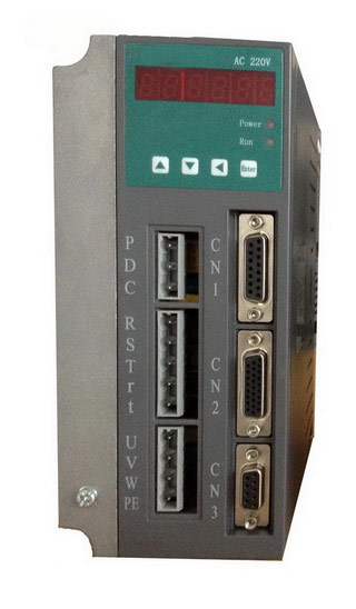 Gozuk synchronous ac servo drive is designed and manufactured, employing the advanced control algorithm based on the market demand, which can realize ...
A BLDC motor may have a trapezoidal Back EMF, there is something called Trapezoidal Motor Control Methodalogy (TRZ). TRZ is an extension of 6-step control ...
Permanent Magnet motors are more efficient than SCIM as the field in the rotor is permanently there. The big advantage for permanent magnet motors is in ...
Gozuk synchronous ac servo drive is designed and manufactured, employing the advanced control algorithm based on the market demand, which can realize ...
A BLDC motor may have a trapezoidal Back EMF, there is something called Trapezoidal Motor Control Methodalogy (TRZ). TRZ is an extension of 6-step control ...
Permanent Magnet motors are more efficient than SCIM as the field in the rotor is permanently there. The big advantage for permanent magnet motors is in ...