Brushless DC Motor Control
A BLDC motor may have a trapezoidal Back EMF, there is something called Trapezoidal Motor Control Methodalogy (TRZ). TRZ is an extension of 6-step control with additional switching states generated to allow winding current to ramp up/down in each phase prior to/after each commutation instant. Trapezoidal motor winding currents, achieve a low noise performance.
Brushless DC motors are generally, although not always, three phase devices. They are wired in either a Y (Wye, Star, T) or Δ (Delta) configuration, but in either case there are three connecting wires, and the current input to any two coils must be output through the third. That is,
C = –(A + B) where A, B, and C are the current flowing through each leg of the 3-phase brushless motor.
The back-emf in a BLDC motor is linearly proportional to the rotational speed of the shaft. The back emf is proportional to the speed of the motor and its direction is given by Flemings right hand rule.
C = –(A + B) simply means that since there is no neutral used the sum of three phase currents must add up to zero
A+B+C=0
Although the drive system is three phase it can be easily simplified and viewed as a Buck Converter fed PMBLDC drive.
<- - Make a Comment - ->
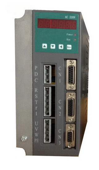
 Servo Motor & Drives