Welcome to ServoMotor.co
I'm in a motor design. Currently, I'm using JMAG Express to estimate the right sizing requirements for a 3-phase Induction Motor that I want to build among friends. As you can see from the picture, I need to be able to reach 3200 RPMs speed, 440 N*m torque and 120kW of max power. I've played around with some of the values in JMAG to reach a weight of around 20kg as you can see from the picture. The low weight is a very important requirement for the project and it should not exceed 50kg. I'm using 48 slots for the stator and 26 for the rotor which is a Caged type. Winding is concentrated with 32 turns.

Assuming that you checked the mechanical properties and the centrifugal force at the rotor at the higher speed from 50Hz to 60Hz,  and they are OK, then you have to consider that the flux in the machine will go down by the ratio of the increase of frequency to 60Hz. Also the inductances will increase, so locked amps will be down, Locked rotor torque will be down, power factor will change, and efficiency will change. No load amps will decrease. If you want to change the electrical design to make it like it was for 50Hz then you have to increase the number of turns of the motor, but you have to know what you are doing.
Please note that except the change in the asynchronous speed of the motor machine, many other parameters will change. This will include the effective phase impedance of the motor, the current/voltage levels, etc. Also, please note that the torque-speed curve and the associated efficiencies will be affected by the change in frequency 60Hz to 50Hz.
and they are OK, then you have to consider that the flux in the machine will go down by the ratio of the increase of frequency to 60Hz. Also the inductances will increase, so locked amps will be down, Locked rotor torque will be down, power factor will change, and efficiency will change. No load amps will decrease. If you want to change the electrical design to make it like it was for 50Hz then you have to increase the number of turns of the motor, but you have to know what you are doing.Please note that except the change in the asynchronous speed of the motor machine, many other parameters will change. This will include the effective phase impedance of the motor, the current/voltage levels, etc. Also, please note that the torque-speed curve and the associated efficiencies will be affected by the change in frequency 60Hz to 50Hz.
In general, the most common failure mode (>> 50%) of low voltage induction motors is bearing failure. Assuming that no special circumstances apply, i.e. no mission critical system, I would recommend to limit preemptive maintenance to vibration monitoring. This can either be done by using accelerometers, i.e. actual measuring the vibration spectrum. Keeping continuous logs of these vibration measurements will give you a good idea of when to expect a failure (and may even allow you to spot motors with broken rotor bars). Vibration monitoring can also be done in a more crude way using your hands and ears, if you do for example a weekly check of your motors.
Electric preemptive tests don't pay off - according to my experience. Winding failures are rather rare and if that happens you have to replace/rewind the motor anyway. Furthermore, none of the mentioned tests will be able to tell you that an electric failure will happen in the near future. A motor may check out perfectly OK today and fail electrically tomorrow. (Online partial discharge testing would perform better in this respect, but is most likely to complex and costly.)
Electric preemptive tests don't pay off - according to my experience. Winding failures are rather rare and if that happens you have to replace/rewind the motor anyway. Furthermore, none of the mentioned tests will be able to tell you that an electric failure will happen in the near future. A motor may check out perfectly OK today and fail electrically tomorrow. (Online partial discharge testing would perform better in this respect, but is most likely to complex and costly.)
Q: I have used only the position control mode only in the servo drive. Can anyone please explain me about speed/velocity control mode in the servo drive, like for the position control mode we will be giving pulse and direction from the external controller, likewise which thing we need to give for speed control mode?
A: Position control in servo motor mean the motor will travel a defined position with some speed. In Position mode u can control both distance & speed by using controller. Position control is used in applications where more accuracy is needed. In Velocity control mode, the speed is controlled by controlling the voltage (0-10V) through external Pot. It is used in a place where controlling is Analog.
For velocity control, you just need to induce an analog signal on the servo drives terminals, and also a zero input command for some brands. This is a lot easier than the position control mode. It's like treating it as an AC variable frequency drive (VFD), only that the servo motor responds more accurately on different speed commands.
Voltage spikes do not usually present a problem in 220V AC drive applications. The reason this is true is that all NEMA standard motors use an insulation that is designed to operate at 600V continuously and withstand intermittent voltage spikes of 1000V (a new motor can often withstand spikes to 1200V). Even if a spike were three times normal peak voltage (325V), it would still be within the 1000V limit. The net result is that standard motors are well suited for operation in 220V AC drive applications as long as the AC drive and motor manufacturer's cable length guidelines are followed. Always consult the manufacturer if the cable between the AC drive and motor will exceed 200 feet. If higher than normal ambient temperatures exist, you may want to upgrade to a motor that uses Class F insulation but, "special" inverter duty insulation is not required.
Unfortunately this is not always the case for 380V applications. Due to the high peak voltage (650V), even relatively small spikes can exceed the 1000V limit of standard motors. If the cable length between the AC drive and a standard motor exceeds 25 feet, a load reactor or dv/dt filter is always recommended. Always follow the manufacturers cable length guidelines closely when using standard motors in 380V AC drive applications.
Unfortunately this is not always the case for 380V applications. Due to the high peak voltage (650V), even relatively small spikes can exceed the 1000V limit of standard motors. If the cable length between the AC drive and a standard motor exceeds 25 feet, a load reactor or dv/dt filter is always recommended. Always follow the manufacturers cable length guidelines closely when using standard motors in 380V AC drive applications.
I used a NEMA-design induction motor, which have fairly high inductance so they can be line-started. I don't recall the inductances, but I made sure to use a motor with a similar power rating to the variable frequency drive.
Don't worry about the inductance without the rotor. If you work through the equations you'll find that the stator R-L time constant dominates the current ripple at the switching frequency. Not enough flux crosses the air-gap at the switching frequency to make much difference.
The rotor does modify the inductance. You will have to be a little careful about how much voltage you apply to the phases, because you can easily generate too much current (a given, since there's no back-emf, either). But at the switching frequency, very little flux crosses the airgap so the rotor does not really figure into the equations for DC bus ripple current. And in this sort of testing, it's DC bus ripple that can accidentally destroy the variable frequency drive you are trying to verify!
I have worked a great deal designing PM synchronous servo motors and their systems. Generally I work with precisions of 20 micron or less, this application is only about 800 micron of positioning accuracy. Following are some of the principles that I use to guide me through applications that might help you.
First- Accuracy is a function of the system not just the motor. The motor is merely a device for converting current into torque or force. Your system is comprised of the following: The Load, this is the mechanical portion of the system including the work and cutters; stiffer is always better when it comes to precision and if your load is too flexible the required precision could be impossible. The Controller/Amplifier this is where the servo loop is closed, system tuning parameters are set and the current is regulated to the motor windings, it is best to speak with a manufacture representative to ensure that you have to correct control for you application as this can be a complex subject. The Encoder or feed-back device, higher resolution is always better; I find I need a minimum of 10x resolution to my desired system accuracy. Finally the Motor, in positioning application I generally find lower inertia is better for accuracy, but in velocity control (which sounds more like what you need) I find higher inertia to be better for accuracy; this is because velocity control applications tend not to need high accelerations or rapid changes in speed, this means high inertia is your friend, it tends to smooth things out and help maintain a constant speed.
First- Accuracy is a function of the system not just the motor. The motor is merely a device for converting current into torque or force. Your system is comprised of the following: The Load, this is the mechanical portion of the system including the work and cutters; stiffer is always better when it comes to precision and if your load is too flexible the required precision could be impossible. The Controller/Amplifier this is where the servo loop is closed, system tuning parameters are set and the current is regulated to the motor windings, it is best to speak with a manufacture representative to ensure that you have to correct control for you application as this can be a complex subject. The Encoder or feed-back device, higher resolution is always better; I find I need a minimum of 10x resolution to my desired system accuracy. Finally the Motor, in positioning application I generally find lower inertia is better for accuracy, but in velocity control (which sounds more like what you need) I find higher inertia to be better for accuracy; this is because velocity control applications tend not to need high accelerations or rapid changes in speed, this means high inertia is your friend, it tends to smooth things out and help maintain a constant speed.
Letters or numbers that are the same would normally go together. Your example is RR, YY, BB. They could be XX, YY, ZZ or 11, 22, 33. This is very often done on larger motors because two smaller cables are easier to handle than one large cable.
With the USA and Canada single speed motors: If you see a numbering system from1-6 it normally means that the motor is designed for a WYE-DELTA Start. If you see a numbering system from 1-9 this would indicate a dual voltage winding with the low voltage being 50% of the high voltage. This termed a 1WYE-2Wye connection or 1Delta-2 Delta. This would indicate a series connection for the high voltage and a parallel connection for the low voltage. The number of parallels can change but the low voltage will always have double the Parallels of the high voltage.
In Europe the main identification is lettering. U-V-W, X-Y-Z or U1, V1, W1 and U2, V2 W2 in the first example U and X are a phase, V and Y are a phase and W and Z are a phase. The phases are normally connected in series, (WYE), for the higher voltage, (possibly 380) and you can connect the phases in Parallel, (Delta) for a rated voltage of 58% of the higher voltage: (220-volts). This is also evident in the medium voltage motors that are rated 2300/4160. Wye Connected for 4160 and Delta connected for 2300. Don't you dare mix them up and connect for the wrong voltage.
Most home and business appliances operate on single phase AC power. For this reason, single-phase AC motors are in widespread use. A single-phase induction motor is larger in size, for the same horsepower, than a three-phase motor. When running, the torque produced by a single phase motor is pulsating and irregular, contributing to a much lower power factor and efficiency than that of a polyphase motor. Single-phase AC motors are generally available in the fractional to 10-hp range and all use a solid squirrel-cage rotor.
The single-phase induction motor operates on the principle of induction, just as does a three-phase motor. Unlike three phase motors, they are not self-starting. Whereas a three-phase induction motor sets up a rotating field that can start the motor, a single-phase motor needs an auxiliary means of starting. Once a single-phase induction motor is running, it develops a rotating magnetic field.
The single-phase induction motor operates on the principle of induction, just as does a three-phase motor. Unlike three phase motors, they are not self-starting. Whereas a three-phase induction motor sets up a rotating field that can start the motor, a single-phase motor needs an auxiliary means of starting. Once a single-phase induction motor is running, it develops a rotating magnetic field.
An induction motor rotor can be either wound rotor or a squirrel cage rotor. The majority of commercial and industrial applications usually involve the use of a three-phase squirrel-cage induction motor. A typical squirrel-cage induction motor is shown. The rotor is constructed using a number of single bars short-circuited by end rings and arranged in a hamster-wheel or squirrel-cage configuration. When voltage is applied to the stator winding, a rotating magnetic field is established. This rotating magnetic field causes a voltage to be induced in the rotor, which, because the rotor bars are essentially single-turn coils, causes currents to flow in the rotor bars. These rotor currents establish their own magnetic field, which interacts with the stator magnetic field to produce a torque. The resultant production of torque spins the rotor in the same direction as the rotation of the magnetic field produced by the stator. In modern induction motors, the most common type of rotor has cast-aluminum conductors and short-circuiting end rings.
In homogenizing manufacturing consistency, the National Electrical Manufacturers Association (NEMA) created a set of standards describing the various sizes of electric motors. NEMA frames are organized into groups where all mounting dimensions are identical.
 The reason for this system allows for substitution of a motor manufactured by one company with a different company, if the frame isn’t unique.
In an excellent article at the Electrical Engineering Portal, Edvard points out the seven common NEMA motor types:
1. Open Drip Proof (ODP)
Allows air to circulate through the windings for cooling, but prevent drops of liquid from falling into motor within a 15 degree angle from vertical. Typically used for indoor applications in relatively clean, dry locations.
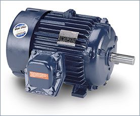
2. Totally Enclosed Fan Cooled (TEFC)
Prevents the free exchange of air between the inside and outside of the frame, but does not make the frame completely air tight. A fan is attached to the shaft and pushes air over the frame during its operation to help in the cooling process.
The ribbed frame is designed to increase the surface area for cooling purposes.
The TEFC style enclosure is the most versatile of all. It is used on pumps, fans, compressors, general industrial belt drive and direct connected equipment.
The reason for this system allows for substitution of a motor manufactured by one company with a different company, if the frame isn’t unique.In an excellent article at the Electrical Engineering Portal, Edvard points out the seven common NEMA motor types:
1. Open Drip Proof (ODP)
Allows air to circulate through the windings for cooling, but prevent drops of liquid from falling into motor within a 15 degree angle from vertical. Typically used for indoor applications in relatively clean, dry locations.
2. Totally Enclosed Fan Cooled (TEFC)
Prevents the free exchange of air between the inside and outside of the frame, but does not make the frame completely air tight. A fan is attached to the shaft and pushes air over the frame during its operation to help in the cooling process.
The ribbed frame is designed to increase the surface area for cooling purposes.
The TEFC style enclosure is the most versatile of all. It is used on pumps, fans, compressors, general industrial belt drive and direct connected equipment.
Synchronous motor technology has its roots in the electricity and magnetism experiments of Michael Faraday in 1830 and his discovery that a changing magnetic field can induce an electric current. Two years later Parisian instrument maker, Hippolyte Pixii, built the first alternator consisting of a revolving horseshoe magnet passing over two wound wire coils generating a simple form of alternating current (AC). During the late 19th century, the advantages of AC over the existing direct current (DC) technology espoused by Thomas Edison, led many inventors in the United States and Europe, such as Nikola Tesla, to advocate the development of AC motors.

A century later, synchronous AC motors still represent one of most widely used technologies. Simply put, a synchronous motor is a rotary motor in which the speed of the rotating part or shaft is in synchrony or spins in tandem with the line frequency oscillations of the supply current (typically 60 Hz in the US and 50 Hz in Europe and Asia). To accomplish this, synchronous motors contain electromagnets usually on the rotor and a winding of a coil of copper wire (aka the field coil) around the stator ring. A small space, or air gap, separates the stator from the rotor, allowing the rotor to spin freely when the supply current is turned on. Depending on design requirements, the location of the electromagnets or field coil are interchangeably mountable on the stator or the rotor. When excited, electromagnets and the field coil work together to create a magnetic field that rotates in time with the oscillations of the line current. The rotor locks in, or turns in step, with this field at the same rate causing the shaft to rotate quickly. Once this occurs, the motor reaches steady-state operation and is in synchrony or “in sync”. If the motor load increases beyond breakdown load, the motor falls out of sync, and the field winding no longer follows the rotating magnetic field.
Synchronous motors are available in low and high horsepower industrial sizes. In low-voltage applications, synchronous motors are in use where precise constant speed is required. Small synchronous motors are able to start without assistance if the moment of inertia of the rotor and its mechanical load is sufficiently small. Small synchronous motors are commonly used in line-powered electric clocks and appliance timers.
A high potential (hipot) test verifies that the insulation of an energized product or component is sufficient to protect the operator, system or connected components from electrical shock.
A typical electric wire has one or two components: a wire conductor along which the current flows, and insulation (aka dielectric) that shields the conductor from direct contact with other wires. Some wires also contain a third component, metallic shielding, between the conductor and the insulation. The question is: will the insulation do the job it was designed to do? If not, its failure could cause injury, loss of life, and damage to expensive equipment along with costly downtime.
A hipot test applies high voltage between a product's current-carrying conductors and its metallic shielding. The hipot tester measures current that flows through the insulation, known as dielectric leakage current. Hence, when a deliberate over-application of test voltage doesn't cause the insulation to break down (in other words if the insulation sufficiently withstands the voltage under normal operating conditions without allowing it to “leak out”), the product is considered safe under normal operating conditions.
Motor Failed…Who Cares?
Too often we hear maintenance & reliability experts downplay the data analysis or testing of motors that have failed from a stator fault. "Why would you need test equipment to test a stator fault?" we might hear. The mistake these "experts" make is to assume that troubleshooting a motor begins with failure analysis. Smart motors are on the market, but we haven't seen any with a big red flag that pops up with the words "STATOR FAULT" when it trips or fails to start. The reality most non-clairvoyant technicians face is they don't know exactly what failed, or if anything failed at all. Is it the motor, the load, the starter or maybe a nuisance trip? Remember a very important role of your predictive technologies is to assist the technicians in a quick recovery effort of production in the unfortunate situation of an unplanned outage. Performing some quick tests such as phase resistance, phase inductance, and ground wall tests can allow the technician to isolate quickly focus on or off of the electric motor and hasten good decision-making in deciding if a repair or replacement is necessary. A simple phase imbalance test may just prevent you from replacing a motor that doesn't need to be replaced.
It's Not Always the Motor's Fault
When testing a motor it is good practice to thoroughly test the entire motor circuit. A Wound Rotor Motor has two circuits – the stator circuit, which is very similar to a standard AC induction motor, and a rotor circuit. The rotor circuit usually consists of rotor windings, rings and brushes, and a resistor bank controlled using contactors. Depending on the application, the rotor circuit is used to control the torque, speed, or startup current of the motor. The external portion of the rotor circuit usually consists of an external resistor bank with a number of resistance steps. An unbalance of resistance in the resistor bank will cause an unbalance of the flux in the rotor creating a situation similar to a broken rotor bar. There are several tests using the MCEMAX that can be performed to evaluate this situation. With the motor de-energized, a standard test can be performed on each step of the resistor bank circuit to ensure resistance is balanced through each step and when the resistor bank is fully shorted out. With the motor running, a rotor evaluation test can be performed to look for a current unbalance during startup and after the motor is at full speed. An In-Rush test can be used to evaluate startup and switching times when troubleshooting anomalies in the rotor circuit.
I was doing some tests the other day on slow speed control (1rpm). I thought that sinusoidal commutation and a high resolution encoder (4K CPT) would be "the thing" for controlling a multi-pole flat motor well (with detent torque - naming the EC90 flat from maxon). This would enable the controller to have better control during the commutation between coil switching. During the commutation the natural attraction of the rotor to the poles pulls and pushes the rotor into position. This is something that I thought sinusoidal commutation would help with. I was pleasantly surprised that using another controller that had just block commutation but a 53.5Khz current loop proved far superior in comparison to the 10KHz control on the sinusoidal drive!
A servo system is a servo system and so where or how it is used, not to oversimplify, it is almost irrelevant to a controls engineer. There are a lot of questions that would have to be answered before either myself or anyone with experience in controls could give you sound advice specific to your project:
This is just to get you started thinking about some basic issues. I have experience with motion controls, but I am not a motion controls expert. A motion controls expert will I am sure, come up with a much more comprehensive list of questions.
As far as servos, if you are looking to learn how to program motion controls, I suggest to look into Yaskawa. Spend a few hours perusing their website. Yaskawa products have very good reputation and they have a large installed base, and, I personally like their website. It has a lot of useful information. I like Allen-Bradley as well, but you should know that I am an Allen-Bradley integrator and channel partner, and so I am somewhat partial to their products. AB stuff is expensive anyway, but for good reason. One of my colleagues for whom I have tremendous respect, with a ton of experience in motion controls is very fond of Copley.
If you Google 'Motion Controls' you'll get a ton of hits and you should find some useful info there as well.
Generally speaking, in my opinion, a big part of anything involving motion; fault handling and recovery, and of course, safety. You absolutely must take safety into consideration when dealing with motion and make it a priority.
- Do you already have an EMAP Servo Press?
- Does it have a servo control system in it already?
- If it does, are you looking to integrate the Press with other automation devices?
- If it doesn't, how many axes do you need?
- Do you need a coordinated motion controller?
This is just to get you started thinking about some basic issues. I have experience with motion controls, but I am not a motion controls expert. A motion controls expert will I am sure, come up with a much more comprehensive list of questions.
As far as servos, if you are looking to learn how to program motion controls, I suggest to look into Yaskawa. Spend a few hours perusing their website. Yaskawa products have very good reputation and they have a large installed base, and, I personally like their website. It has a lot of useful information. I like Allen-Bradley as well, but you should know that I am an Allen-Bradley integrator and channel partner, and so I am somewhat partial to their products. AB stuff is expensive anyway, but for good reason. One of my colleagues for whom I have tremendous respect, with a ton of experience in motion controls is very fond of Copley.
If you Google 'Motion Controls' you'll get a ton of hits and you should find some useful info there as well.
Generally speaking, in my opinion, a big part of anything involving motion; fault handling and recovery, and of course, safety. You absolutely must take safety into consideration when dealing with motion and make it a priority.
A servo drive system, as opposed to a variable frequency drive (VFD) or AC motor drive (AMD), has the ability to position with extreme precision and repeatability. While a VFD or AMD can be configured for position control, it cannot attain the exactness of a servo drive. VFD's and AMD's are also available in much higher horsepower ranges than servo's. Selection of external feedback sensors such as encoders, resolvers, linear position sensors, etc., required to achieve closed-loop control and each having its own inherent precision, will enable the system accuracy accordingly. Your application requirements will always dictate which system configuration will give you the best results!
Many of today's VFDs are fully capable of doing positioning when using encoder feedback; as with many other things, the lines have become blurred. What separates servo motor from induction motors is their low inertia and their ability to accelerate and decelerate much faster, the trick is to decide when you need full servo performance.
Many of today's VFDs are fully capable of doing positioning when using encoder feedback; as with many other things, the lines have become blurred. What separates servo motor from induction motors is their low inertia and their ability to accelerate and decelerate much faster, the trick is to decide when you need full servo performance.
 Servo Motor & Drives
Category
Featured
Assuming that you checked the mechanical properties and the centrifugal force at the rotor at the higher speed from 50Hz to 60Hz, and they are OK, then ...
The troubleshooting guide outlines a comprehensive variety of motor problems. Generally the categories are arranged according to symptoms offering brief ...
The main difference between AC and DC motors is that the magnetic field generated by the stator rotates in the case of AC motors. A rotating magnetic ...
 First, 7 things to consider when choosing an electric motor: Choosing the right motor isn’t always straightforward. There are so many variables to ...
Induction motors operate on the principal of current induction in the rotor which must rotate at a speed less than synchronous speed for induction to ...
First, 7 things to consider when choosing an electric motor: Choosing the right motor isn’t always straightforward. There are so many variables to ...
Induction motors operate on the principal of current induction in the rotor which must rotate at a speed less than synchronous speed for induction to ...
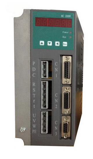 Gozuk synchronous ac servo drive is designed and manufactured, employing the advanced control algorithm based on the market demand, which can realize ...
A BLDC motor may have a trapezoidal Back EMF, there is something called Trapezoidal Motor Control Methodalogy (TRZ). TRZ is an extension of 6-step control ...
Permanent Magnet motors are more efficient than SCIM as the field in the rotor is permanently there. The big advantage for permanent magnet motors is in ...
Gozuk synchronous ac servo drive is designed and manufactured, employing the advanced control algorithm based on the market demand, which can realize ...
A BLDC motor may have a trapezoidal Back EMF, there is something called Trapezoidal Motor Control Methodalogy (TRZ). TRZ is an extension of 6-step control ...
Permanent Magnet motors are more efficient than SCIM as the field in the rotor is permanently there. The big advantage for permanent magnet motors is in ...