AC motor
Assuming that you checked the mechanical properties and the centrifugal force at the rotor at the higher speed from 50Hz to 60Hz,  and they are OK, then you have to consider that the flux in the machine will go down by the ratio of the increase of frequency to 60Hz. Also the inductances will increase, so locked amps will be down, Locked rotor torque will be down, power factor will change, and efficiency will change. No load amps will decrease. If you want to change the electrical design to make it like it was for 50Hz then you have to increase the number of turns of the motor, but you have to know what you are doing.
Please note that except the change in the asynchronous speed of the motor machine, many other parameters will change. This will include the effective phase impedance of the motor, the current/voltage levels, etc. Also, please note that the torque-speed curve and the associated efficiencies will be affected by the change in frequency 60Hz to 50Hz.
and they are OK, then you have to consider that the flux in the machine will go down by the ratio of the increase of frequency to 60Hz. Also the inductances will increase, so locked amps will be down, Locked rotor torque will be down, power factor will change, and efficiency will change. No load amps will decrease. If you want to change the electrical design to make it like it was for 50Hz then you have to increase the number of turns of the motor, but you have to know what you are doing.Please note that except the change in the asynchronous speed of the motor machine, many other parameters will change. This will include the effective phase impedance of the motor, the current/voltage levels, etc. Also, please note that the torque-speed curve and the associated efficiencies will be affected by the change in frequency 60Hz to 50Hz.
Voltage spikes do not usually present a problem in 220V AC drive applications. The reason this is true is that all NEMA standard motors use an insulation that is designed to operate at 600V continuously and withstand intermittent voltage spikes of 1000V (a new motor can often withstand spikes to 1200V). Even if a spike were three times normal peak voltage (325V), it would still be within the 1000V limit. The net result is that standard motors are well suited for operation in 220V AC drive applications as long as the AC drive and motor manufacturer's cable length guidelines are followed. Always consult the manufacturer if the cable between the AC drive and motor will exceed 200 feet. If higher than normal ambient temperatures exist, you may want to upgrade to a motor that uses Class F insulation but, "special" inverter duty insulation is not required.
Unfortunately this is not always the case for 380V applications. Due to the high peak voltage (650V), even relatively small spikes can exceed the 1000V limit of standard motors. If the cable length between the AC drive and a standard motor exceeds 25 feet, a load reactor or dv/dt filter is always recommended. Always follow the manufacturers cable length guidelines closely when using standard motors in 380V AC drive applications.
Unfortunately this is not always the case for 380V applications. Due to the high peak voltage (650V), even relatively small spikes can exceed the 1000V limit of standard motors. If the cable length between the AC drive and a standard motor exceeds 25 feet, a load reactor or dv/dt filter is always recommended. Always follow the manufacturers cable length guidelines closely when using standard motors in 380V AC drive applications.
Most home and business appliances operate on single phase AC power. For this reason, single-phase AC motors are in widespread use. A single-phase induction motor is larger in size, for the same horsepower, than a three-phase motor. When running, the torque produced by a single phase motor is pulsating and irregular, contributing to a much lower power factor and efficiency than that of a polyphase motor. Single-phase AC motors are generally available in the fractional to 10-hp range and all use a solid squirrel-cage rotor.
The single-phase induction motor operates on the principle of induction, just as does a three-phase motor. Unlike three phase motors, they are not self-starting. Whereas a three-phase induction motor sets up a rotating field that can start the motor, a single-phase motor needs an auxiliary means of starting. Once a single-phase induction motor is running, it develops a rotating magnetic field.
The single-phase induction motor operates on the principle of induction, just as does a three-phase motor. Unlike three phase motors, they are not self-starting. Whereas a three-phase induction motor sets up a rotating field that can start the motor, a single-phase motor needs an auxiliary means of starting. Once a single-phase induction motor is running, it develops a rotating magnetic field.
The main difference between AC and DC motors is that the magnetic field generated by the stator rotates in the case of AC motors. A rotating magnetic field is key to the operation of all AC motors. The principle is simple. A magnetic field in the stator is made to rotate electrically around and around in a circle. Another magnetic field in the rotor is made to follow the rotation of this field pattern by being attracted and repelled by the stator field. Because the rotor is free to turn, it follows the rotating magnetic field in the stator.
It illustrates the concept of a rotating magnetic field as it applies to the stator of a three-phase AC motor. The operation can be summarized as follows:
It illustrates the concept of a rotating magnetic field as it applies to the stator of a three-phase AC motor. The operation can be summarized as follows:
- Three sets of windings are placed 120 electrical degrees apart with each set connected to one phase of the three-phase power supply.
- When three-phase current passes through the stator windings, a rotating magnetic field effect is produced that travels around the inside of the stator core.
- Polarity of the rotating magnetic field is shown at six selected positions marked off at 60 degree intervals on the sine waves representing the current flowing in the three phases, A, B, and C.
- In the example shown, the magnetic field will rotate around the stator in a clockwise direction.
- Simply interchanging any two of the three-phase power input leads to the stator windings reverses direction of rotation of the magnetic field.
- The number of poles is determined by how many times a phase winding appears. In this example, each winding appears twice, so this is a two-pole stator.
First, 7 things to consider when choosing an electric motor:
Choosing the right motor isn’t always straightforward. There are so many variables to consider that it can be hard to know where to start. The wrong motor can result in a myriad of problems, and can ultimately cause application failure.
(Here are) some initial questions that you need to answer before attempting to find the right motor for your project.
Questions you need to consider in choosing a motor:
Speed: How fast should the motor be able to run? Torque: Which motors provide enough torque? Size: What are the size restrictions? Precision: Does the motor need to be accurate? How accurate? Environment: What is the environment in which the motor will be running (is there dust, moisture, air flow, etc.)? Communication: How do you want to communicate with the motor? Cost: What is your budget?
Once you’ve come up with answers to these preliminary questions, you can begin to figure out the best option for your application.
I'd be very careful about surge testing motors in industrial environments. There is specific guidance from IEEE, NEMA and EASA that talks about surge testing being potentially destructive when done on motors in the field. More specifically, motors with unknown insulation conditions. Surge and hi pot testing are geared for shop testing on repaired or new motors. I'd recommend monitoring online impedance imbalance and current imbalance. We've seen many case studies where these two parameters were early indicators of stator faults. I agree that offline, phase to phase resistance and inductance can be great indicators of stator faults. The downside of offline testing is the fact the motor has to be shutdown.
We also recommend looking for faults conducive to stator failures. For example, if you have a high restive imbalance on the circuit this can increase heat inside the motor. The increased heat further stresses the insulation system and can lead to bigger insulation or stator failures. If we could have found the small problem, ie. resistance imbalance, then we could have prevented the stator fault.
Stator is a tricky fault zone because faults typically develop so quickly. With a good overall motor testing program you can find the faults that lead to stator issues and get them corrected early.
I was trying to point out that impedance imbalance and current imbalance can act as good indicators for stator issues. It seemed to me that most people in the discussion we're focusing on offline tests and there wasn't much mention of online stator testing.
I am not a manufacturer of motors, except for the modification of specialty applications. For example we changed out several hundred motors for the National Weather Service contained in a dipole antenna body. Existing motor was a single phase permanent split capacitor synchronous motor, 110 volt, 1800 RPM DESIRED, due to a feedback tachometer mounted on the motor to verify the speed as these receivers accepted upper air feedback of weather conditions, from weather balloons launched two to three times a day. Location and tracking of the balloons were critical, if the tach feedback was off by one rpm [from 1800] the tracking electronics could not deal with the inconsistency.
I attempted to purchase motors for this application, but because the motor was mounted vertically in a solid cone, no ventilation, plus they were single phase, with induction synchronous rotors, voltage was a consideration, and the units were mounted from Hawaii to Guam to Florida, across the US and Territories.
I took the existing single phase PSC SYNCH MOTOR, which few ever had the torque, or would stay at 1800 rpm, or fail do to the heat.
While they only needed around 300 plus active motors, they needed half as many as spares, considering the past history of failures and the lack of ability to deliver accurate timely weather data over an exact path.
It was not a case of excessive NOISE, it was a case of perceived sound, it sounded different, so for those involved with any Governmental Agency knows that form, fit, function is their mantra and excuse to not accept anything.
We had several complaints of noise, turns out the noise was in no way a danger or at levels of any concern, just different.
While testing 4. 6. 8. 2 pole motors for "noise" in a controlled environment, is only data from those conditions, out in the wild west, those conditions are going to change, mounting, structure, all explained above will affect the motor's "noise" levels, or perceived "noise" levels.
In the fact that no load, [NEMA] testing is not going to be exacting as other possible more exacting, different parameter type testing, if noise is a concern, is under full load, which again is a variable.
Individual organizations should consider developing their own customized Motor Management plan and policy. Some of the factors to consider are: extent of the repair - is it bearings or rewind, lead time for repair vs replace (special builds vs off the shelf), cost of new vs repair, single phase vs three phase, size (HP) of the product, efficiency of the failed motor vs efficiency of the replacement motor, warranty of the new vs repaired. Each organization's criteria and situation will factor into their individual decision tree.
Before you establish what %HP of the new motor value you will spend on repair, you need to know your repair facility. Derek is correct when he says that your service center needs to be following the "EASA AR-100 Recommended Practices". Following these repair guidelines, you will not lose efficiency in the repair process, in fact on larger HP's, there maybe opportunities to gain efficiency if your EASA shop gets EASA engineering involved. Additionally, the repair center should have a recognized and accredited Quality Assurance Program, such as ISO 9000. Weighing in on your decision, compare the new motor to what you are going to get back. Typically a new Nema T frame motor will be insulation Class F (155' C), many EASA facilities will rewind with insulation Class H (180' C) and you will immediately have a 25' C advantage over new. Also, a qualified individual rewinding at an EASA repair facility is (highly) likely to produce greater quality than the factory cranking out "production". Balance standards are also typically better which will yield longer bearing life when the motor is back in service.
Before you establish what %HP of the new motor value you will spend on repair, you need to know your repair facility. Derek is correct when he says that your service center needs to be following the "EASA AR-100 Recommended Practices". Following these repair guidelines, you will not lose efficiency in the repair process, in fact on larger HP's, there maybe opportunities to gain efficiency if your EASA shop gets EASA engineering involved. Additionally, the repair center should have a recognized and accredited Quality Assurance Program, such as ISO 9000. Weighing in on your decision, compare the new motor to what you are going to get back. Typically a new Nema T frame motor will be insulation Class F (155' C), many EASA facilities will rewind with insulation Class H (180' C) and you will immediately have a 25' C advantage over new. Also, a qualified individual rewinding at an EASA repair facility is (highly) likely to produce greater quality than the factory cranking out "production". Balance standards are also typically better which will yield longer bearing life when the motor is back in service.
It appears like many contributors treat this application as if it is a distribution board that is to be supplied by a 400m cable connection. That must be the reason why so many calls for a neutral, or earth return core, as well as for the very limited allowed voltage drop during start. In many applications we directly recommend reducing the terminal voltage during start, for a number of reasons, so why should it all of a sudden become detrimental in this situation? The motor has no way of knowing what has caused the reduced starting voltage anyway! As long as there is sufficient voltage to get the drive to start within a reasonable time, the start VD should cause no headache.
One important issue that has only been briefly touched upon by a single contributor is the economy: It should be our professional endeavour to make the total cost of ownership as low as possible, so it would be reasonable to include energy cost into the equation. The heavier cable as proposed by many, will obviously reduce the running losses considerably as compared to the smallest cable that will satisfy the technical requirements.
If this motor is intended to run for only brief periods each day, or maybe for only a few days or months, it will be bad economy to choose the heavy cable just because you can. Likewise, if this installation is part of a quotation, you could very well miss out on a much larger contract, because most clients will only look at the total sum, before addressing any technical issues.
Theoretically, Yes, if the conditions under which it's running are constant (on squirrel cage induction motors). In reality, it varies due to a variety of factors. These can include changes in load, input power, environmental conditions, etc. Speed control really has 2 effects - providing a wider range of speed capabilities with the same motor (adjustability) as well as smoothing out (or at least attempting to smooth out) the effects that would change the motor speed and transients in loading, input voltage, etc.
Practically, NO, for electric motors connected to the AC power line. The speed of an AC induction motor is a function of the AC frequency, the number of poles in the motor, and the load on the motor. Under no-load conditions, the speed is quite constant. Under load, the speed will vary since the motor torque comes from the lag in the phase current. Unless the motor runs slower than synchronous speed, it cannot produce the torque necessary to do its work. Synchronous motors run at constant speed.
Practically, NO, for electric motors connected to the AC power line. The speed of an AC induction motor is a function of the AC frequency, the number of poles in the motor, and the load on the motor. Under no-load conditions, the speed is quite constant. Under load, the speed will vary since the motor torque comes from the lag in the phase current. Unless the motor runs slower than synchronous speed, it cannot produce the torque necessary to do its work. Synchronous motors run at constant speed.
Induction motors operate on the principal of current induction in the rotor which must rotate at a speed less than synchronous speed for induction to occur. This is referred to as slip speed and should not be confused with pole slipping.
Why induction motors have no pole slipping and why other motors have pole slipping. I will attempt to answer this but first let's define poles and synchronous speed in regards to electric motor operation.
Poles in an electric motor refer to the magnetic circuit poles and come in sets of two just like a common magnet. One is north (N) and one is south (S). If a motor has two poles, it will have one N-pole and one S-pole. If the motor has four poles, it will have 2 N-poles and 2 S-poles and so on.
Synchronous speed in an electric motor is the speed that is produced by the traveling magnetic filed wave as it rotates around the stator magnetic circuit. The synchronous speed of a motor is equal to 120*f/p where f = the system frequency in Hz and p is equal to the number of poles in the motor.
All AC motors have two basic parts: (1) a stator winding and iron core and (2) a rotor winding and iron core that is free to rotate and is connected to the motor shaft. For a 3-phase induction motor, when the stator is energized by a three phase voltage source, a magnetic field will be produced that rotates at synchronous speed. As this magnetic flux cuts across the rotor winding it induces a current (via Faraday's law of induction) in the rotor winding which intern produces a second magnetic flux. These two magnetic fluxes both rotate at synchronous speed and couple together like two magnets and thus transfer torque directly to the rotor shaft.
BLDC was coined as when using the standard "six step" energisation it really is very similar to the action carried out by the commutator in a brushed motor. The motor is of course an AC motor but in terms of the BEMF waveform shape it MAY (underlined!!) have been designed with a more trapezoidal BEMF which CAN (underlined!!) give a smoother torque compared with a sine BEMF and six step energisation.
The current through the windings can be anything you want. Preferably you are driving a synchronous motor (that is NOT BLDC) with a sinusoidal current to get a sinusoidal voltage across the windings, what the synchronous motor is designed for. The current through the BLDC motor usually has the form of a "modified" square wave. The current through each winding is either steady positive, zero or steady negative. It is during the zero period you read the BEMF from that winding to establish the rotor location for a sensorless BLDC so you (that is the controller) can switch the current through the windings at the right time.
The current through the windings can be anything you want. Preferably you are driving a synchronous motor (that is NOT BLDC) with a sinusoidal current to get a sinusoidal voltage across the windings, what the synchronous motor is designed for. The current through the BLDC motor usually has the form of a "modified" square wave. The current through each winding is either steady positive, zero or steady negative. It is during the zero period you read the BEMF from that winding to establish the rotor location for a sensorless BLDC so you (that is the controller) can switch the current through the windings at the right time.
 Servo Motor & Drives
Category
Featured
Assuming that you checked the mechanical properties and the centrifugal force at the rotor at the higher speed from 50Hz to 60Hz, and they are OK, then ...
The troubleshooting guide outlines a comprehensive variety of motor problems. Generally the categories are arranged according to symptoms offering brief ...
The main difference between AC and DC motors is that the magnetic field generated by the stator rotates in the case of AC motors. A rotating magnetic ...
First, 7 things to consider when choosing an electric motor: Choosing the right motor isn’t always straightforward. There are so many variables to ...
Induction motors operate on the principal of current induction in the rotor which must rotate at a speed less than synchronous speed for induction to ...
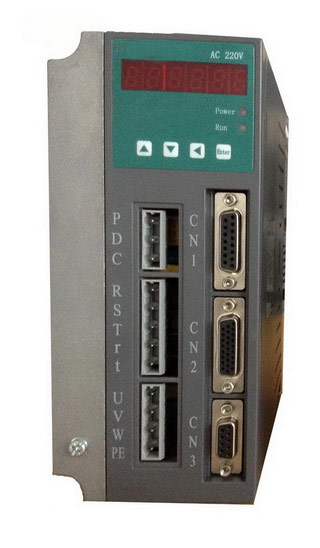 Gozuk synchronous ac servo drive is designed and manufactured, employing the advanced control algorithm based on the market demand, which can realize ...
A BLDC motor may have a trapezoidal Back EMF, there is something called Trapezoidal Motor Control Methodalogy (TRZ). TRZ is an extension of 6-step control ...
Permanent Magnet motors are more efficient than SCIM as the field in the rotor is permanently there. The big advantage for permanent magnet motors is in ...
Gozuk synchronous ac servo drive is designed and manufactured, employing the advanced control algorithm based on the market demand, which can realize ...
A BLDC motor may have a trapezoidal Back EMF, there is something called Trapezoidal Motor Control Methodalogy (TRZ). TRZ is an extension of 6-step control ...
Permanent Magnet motors are more efficient than SCIM as the field in the rotor is permanently there. The big advantage for permanent magnet motors is in ...