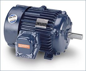
Squirrel Cage Induction Motor
An induction motor rotor can be either wound rotor or a squirrel cage rotor. The majority of commercial and industrial applications usually involve the use of a three-phase squirrel-cage induction motor. A typical squirrel-cage induction motor is shown. The rotor is constructed using a number of single bars short-circuited by end rings and arranged in a hamster-wheel or squirrel-cage configuration. When voltage is applied to the stator winding, a rotating magnetic field is established. This rotating magnetic field causes a voltage to be induced in the rotor, which, because the rotor bars are essentially single-turn coils, causes currents to flow in the rotor bars. These rotor currents establish their own magnetic field, which interacts with the stator magnetic field to produce a torque. The resultant production of torque spins the rotor in the same direction as the rotation of the magnetic field produced by the stator. In modern induction motors, the most common type of rotor has cast-aluminum conductors and short-circuiting end rings.
The resistance of the squirrel-cage rotor has an important effect on the operation of the motor. A high-resistance rotor develops a high starting torque at low starting cur rent. A low-resistance rotor develops low slip and high efficiency at full load. Ill. 36 shows how motor torque varies with rotor speed for three NEMA-type squirrel-cage induction motors:
NEMA Design B - Considered a standard type with normal starting torque, low starting current, and low slip at full load. Suitable for a broad variety of applications, such as fans and blowers, that require normal starting torque.
NEMA Design C -This type has higher than standard rotor resistance, which improves the rotor power factor at start, providing more starting torque. When loaded, however, this extra resistance causes a greater amount of slip. Used for equipment, such as a pump, that requires a high starting torque.
NEMA Design D -The even higher rotor resistance of this type produces a maximum amount of starting torque. This type is suitable for equipment with very high inertia starts such as cranes and hoists.
Operating characteristics of the squirrel-cage motor include the following:
If the rotor turned at the same speed at which the field rotates, there would be no relative motion between the rotor and the field and no voltage induced. Because the rotor slips with respect to the rotating magnetic field of the stator, voltage and current are induced in the rotor.
The difference between the speed of the rotating magnetic field and the rotor in an induction motor is known as slip and is expressed as a percentage of the synchronous speed as follows:
Percent slip = [Synchronous speed - Actual speed / Synchronous speed ] × 100
The slip increases with load and is necessary to produce useful torque. The usual amount of slip in a 60-Hz, three-phase motor is 2 or 3 %.
===
Problem: Determine the percent slip of an induction motor having a synchronous speed of 1,800 rpm and a rated actual speed of 1,750 rpm.
Solution: Percent slip = Synchronous speed - Actual speed/Synchronous speed × 100 = 1,800 - 1,750/ 1,800 × 100 = 2.78%
===
Loading of an induction motor is similar to that of a transformer in that the operation of both involves changing flux linkages with respect to a primary (stator) winding and secondary (rotor) winding. The no-load current is low and similar to the exciting current in a transformer.
Thus, it's composed of a magnetizing component that creates the revolving flux and a small active component that supplies the windage and friction losses in the rotor plus the iron losses in the stator. When the induction motor is under load, the rotor current develops a flux that opposes and, therefore, weakens the stator flux. This allows more current to flow in the stator windings, just as an increase in the current in the secondary of a transformer results in a corresponding increase in the primary current.
You may recall that power factor (PF) is defined as the ratio of the actual (or true) power (watts) to the apparent power (volt-amperes) and is a measure of how effectively the current drawn by a motor is converted into useful work. The motor exciting current and reactive power under load remain about the same as at no load. For this reason, whenever a motor is operating with no load, the power factor is very low in comparison to when it's operating at full load. At full load the PF ranges from 70% for small motors to 90 % for larger motors.
Induction motors operate at their peak efficiency if they are sized correctly for the load that they will drive. Over sized motors not only operate inefficiently, but they also carry a higher first cost than right-sized units.
The moment a motor is started, during the acceleration period, the motor draws a high inrush current. This inrush current is also called the locked-rotor current. Common induction motors, started at rated voltage, have locked-rotor starting currents of up to 6 times their nameplate full load current. The locked-rotor current depends largely on the type of rotor bar design and can be determined from the NEMA design code letters listed on the nameplate.
High locked-rotor motor current can create voltage sags or dips in the power lines, which may cause objectionable light flicker and problems with other operating equipment. Also, a motor that draws excessive current under locked-rotor conditions is more likely to cause nuisance tripping of protection devices during motor start-ups.
A single-speed motor has one rated speed at which it runs when supplied with the nameplate voltage and frequency. A multispeed motor will run at more than one speed, depending on how the windings are connected to form a different number of magnetic poles. Two-speed, single-winding motors are called consequent pole motors. The low speed on a single-winding consequent pole motor is always one-half of the higher speed. If requirements dictate speeds of any other ratio, a two winding motor must be used. With separate winding motors a separate winding is installed in the motor for each desired speed.
Consequent pole single-winding motors have their stator windings arranged so that the number of poles can be changed by reversing some of the coil currents.
By making the designated connections to these leads, the windings can be connected in series delta or parallel wye.
The series delta connection results in low speed and the parallel wye in high speed. The torque rating would be the same at both speeds. If the winding is such that the series delta connection gives the high speed and the parallel wye connection the low speed, the horsepower rating is the same at both speeds.
Single-speed AC induction motors are frequently supplied with multiple external leads for various voltage ratings in fixed-frequency applications. The multiple leads may be designed to allow either series to parallel reconnections, wye to delta reconnections, or combinations of these.
Typical connections for dual-voltage wye and delta series and parallel reconnections. These types of reconnections should not be confused with the reconnection of multispeed polyphase induction motors. In the case of multispeed motors, the reconnection results in a motor with a different number of magnetic poles and therefore a different synchronous speed at a given frequency.
The resistance of the squirrel-cage rotor has an important effect on the operation of the motor. A high-resistance rotor develops a high starting torque at low starting cur rent. A low-resistance rotor develops low slip and high efficiency at full load. Ill. 36 shows how motor torque varies with rotor speed for three NEMA-type squirrel-cage induction motors:
NEMA Design B - Considered a standard type with normal starting torque, low starting current, and low slip at full load. Suitable for a broad variety of applications, such as fans and blowers, that require normal starting torque.
NEMA Design C -This type has higher than standard rotor resistance, which improves the rotor power factor at start, providing more starting torque. When loaded, however, this extra resistance causes a greater amount of slip. Used for equipment, such as a pump, that requires a high starting torque.
NEMA Design D -The even higher rotor resistance of this type produces a maximum amount of starting torque. This type is suitable for equipment with very high inertia starts such as cranes and hoists.
Operating characteristics of the squirrel-cage motor include the following:
- The motor normally operates at essentially constant speed, close to the synchronous speed.
- Large starting currents required by this motor can result in line voltage fluctuations.
- Interchanging any two of the three main power lines to the motor reverses the direction of rotation.
- Once started, the motor will continue to run, with a phase loss, as a single-phase motor. The current drawn from the remaining two lines will almost double, and the motor will overheat. The motor won't start from standstill if it has lost a phase.
If the rotor turned at the same speed at which the field rotates, there would be no relative motion between the rotor and the field and no voltage induced. Because the rotor slips with respect to the rotating magnetic field of the stator, voltage and current are induced in the rotor.
The difference between the speed of the rotating magnetic field and the rotor in an induction motor is known as slip and is expressed as a percentage of the synchronous speed as follows:
Percent slip = [Synchronous speed - Actual speed / Synchronous speed ] × 100
The slip increases with load and is necessary to produce useful torque. The usual amount of slip in a 60-Hz, three-phase motor is 2 or 3 %.
===
Problem: Determine the percent slip of an induction motor having a synchronous speed of 1,800 rpm and a rated actual speed of 1,750 rpm.
Solution: Percent slip = Synchronous speed - Actual speed/Synchronous speed × 100 = 1,800 - 1,750/ 1,800 × 100 = 2.78%
===
Loading of an induction motor is similar to that of a transformer in that the operation of both involves changing flux linkages with respect to a primary (stator) winding and secondary (rotor) winding. The no-load current is low and similar to the exciting current in a transformer.
Thus, it's composed of a magnetizing component that creates the revolving flux and a small active component that supplies the windage and friction losses in the rotor plus the iron losses in the stator. When the induction motor is under load, the rotor current develops a flux that opposes and, therefore, weakens the stator flux. This allows more current to flow in the stator windings, just as an increase in the current in the secondary of a transformer results in a corresponding increase in the primary current.
You may recall that power factor (PF) is defined as the ratio of the actual (or true) power (watts) to the apparent power (volt-amperes) and is a measure of how effectively the current drawn by a motor is converted into useful work. The motor exciting current and reactive power under load remain about the same as at no load. For this reason, whenever a motor is operating with no load, the power factor is very low in comparison to when it's operating at full load. At full load the PF ranges from 70% for small motors to 90 % for larger motors.
Induction motors operate at their peak efficiency if they are sized correctly for the load that they will drive. Over sized motors not only operate inefficiently, but they also carry a higher first cost than right-sized units.
The moment a motor is started, during the acceleration period, the motor draws a high inrush current. This inrush current is also called the locked-rotor current. Common induction motors, started at rated voltage, have locked-rotor starting currents of up to 6 times their nameplate full load current. The locked-rotor current depends largely on the type of rotor bar design and can be determined from the NEMA design code letters listed on the nameplate.
High locked-rotor motor current can create voltage sags or dips in the power lines, which may cause objectionable light flicker and problems with other operating equipment. Also, a motor that draws excessive current under locked-rotor conditions is more likely to cause nuisance tripping of protection devices during motor start-ups.
A single-speed motor has one rated speed at which it runs when supplied with the nameplate voltage and frequency. A multispeed motor will run at more than one speed, depending on how the windings are connected to form a different number of magnetic poles. Two-speed, single-winding motors are called consequent pole motors. The low speed on a single-winding consequent pole motor is always one-half of the higher speed. If requirements dictate speeds of any other ratio, a two winding motor must be used. With separate winding motors a separate winding is installed in the motor for each desired speed.
Consequent pole single-winding motors have their stator windings arranged so that the number of poles can be changed by reversing some of the coil currents.
By making the designated connections to these leads, the windings can be connected in series delta or parallel wye.
The series delta connection results in low speed and the parallel wye in high speed. The torque rating would be the same at both speeds. If the winding is such that the series delta connection gives the high speed and the parallel wye connection the low speed, the horsepower rating is the same at both speeds.
Single-speed AC induction motors are frequently supplied with multiple external leads for various voltage ratings in fixed-frequency applications. The multiple leads may be designed to allow either series to parallel reconnections, wye to delta reconnections, or combinations of these.
Typical connections for dual-voltage wye and delta series and parallel reconnections. These types of reconnections should not be confused with the reconnection of multispeed polyphase induction motors. In the case of multispeed motors, the reconnection results in a motor with a different number of magnetic poles and therefore a different synchronous speed at a given frequency.
<- - Make a Comment - ->
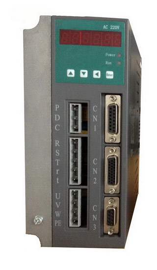
 Servo Motor & Drives