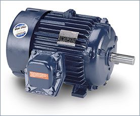
Three phase motor
I'm in a motor design. Currently, I'm using JMAG Express to estimate the right sizing requirements for a 3-phase Induction Motor that I want to build among friends. As you can see from the picture, I need to be able to reach 3200 RPMs speed, 440 N*m torque and 120kW of max power. I've played around with some of the values in JMAG to reach a weight of around 20kg as you can see from the picture. The low weight is a very important requirement for the project and it should not exceed 50kg. I'm using 48 slots for the stator and 26 for the rotor which is a Caged type. Winding is concentrated with 32 turns.

Letters or numbers that are the same would normally go together. Your example is RR, YY, BB. They could be XX, YY, ZZ or 11, 22, 33. This is very often done on larger motors because two smaller cables are easier to handle than one large cable.
With the USA and Canada single speed motors: If you see a numbering system from1-6 it normally means that the motor is designed for a WYE-DELTA Start. If you see a numbering system from 1-9 this would indicate a dual voltage winding with the low voltage being 50% of the high voltage. This termed a 1WYE-2Wye connection or 1Delta-2 Delta. This would indicate a series connection for the high voltage and a parallel connection for the low voltage. The number of parallels can change but the low voltage will always have double the Parallels of the high voltage.
In Europe the main identification is lettering. U-V-W, X-Y-Z or U1, V1, W1 and U2, V2 W2 in the first example U and X are a phase, V and Y are a phase and W and Z are a phase. The phases are normally connected in series, (WYE), for the higher voltage, (possibly 380) and you can connect the phases in Parallel, (Delta) for a rated voltage of 58% of the higher voltage: (220-volts). This is also evident in the medium voltage motors that are rated 2300/4160. Wye Connected for 4160 and Delta connected for 2300. Don't you dare mix them up and connect for the wrong voltage.
The three-phase synchronous motor is a unique and specialized motor. As the name suggests, this motor runs at a constant speed from no load to full load in synchronism with line frequency. As in squirrel-cage induction motors, the speed of a synchronous motor is determined by the number of pairs of poles and the line frequency.
The operation of a typical three-phase synchronous motor can be summarized as follows:
The operation of a typical three-phase synchronous motor can be summarized as follows:
- Three-phase AC voltage is applied to the stator windings and a rotating magnetic field is produced.
- DC voltage is applied to the rotor winding and a second magnetic field is produced.
- The rotor then acts like a magnet and is attracted by the rotating stator field.
- This attraction exerts a torque on the rotor and causes it to rotate at the synchronous speed of the rotating stator field.
- The rotor does not require the magnetic induction from the stator field for its excitation. As a result, the motor has zero slip compared to the induction motor, which requires slip in order to produce torque.
The main difference between AC and DC motors is that the magnetic field generated by the stator rotates in the case of AC motors. A rotating magnetic field is key to the operation of all AC motors. The principle is simple. A magnetic field in the stator is made to rotate electrically around and around in a circle. Another magnetic field in the rotor is made to follow the rotation of this field pattern by being attracted and repelled by the stator field. Because the rotor is free to turn, it follows the rotating magnetic field in the stator.
It illustrates the concept of a rotating magnetic field as it applies to the stator of a three-phase AC motor. The operation can be summarized as follows:
It illustrates the concept of a rotating magnetic field as it applies to the stator of a three-phase AC motor. The operation can be summarized as follows:
- Three sets of windings are placed 120 electrical degrees apart with each set connected to one phase of the three-phase power supply.
- When three-phase current passes through the stator windings, a rotating magnetic field effect is produced that travels around the inside of the stator core.
- Polarity of the rotating magnetic field is shown at six selected positions marked off at 60 degree intervals on the sine waves representing the current flowing in the three phases, A, B, and C.
- In the example shown, the magnetic field will rotate around the stator in a clockwise direction.
- Simply interchanging any two of the three-phase power input leads to the stator windings reverses direction of rotation of the magnetic field.
- The number of poles is determined by how many times a phase winding appears. In this example, each winding appears twice, so this is a two-pole stator.
In theory, it is possible to control the rotor flux vector in any n-phase machine. People play with five and six phase machines all the time but the single phase machine seems to be the singularity because of the bidirectional air gap flux. I think mathematically we can work out some way of controlling that flux but as others have said here, why bother?
One more assumption that I see is that the single phase machine is incapable of higher powers. The single phase machine can be designed to very high powers, but we don't do it because the machines would be much larger than a 3 phase machine and take up more material. In fact there are relatively large single phase machines in the integral power range, designed mainly for rural use, where three phase power is not available.
Capacitor start single phase motors have a stationary switch & centrifugal switch that switch the motor out of the start winding to the run winding. The centrifugal switch requires the rotor to turn at a certain speed (apprx. 3/4 speed) to engage the contacts on the stationary switch. Its possible the motor would never get out of the start winding and quickly fry.
 Servo Motor & Drives
Category
Featured
 Assuming that you checked the mechanical properties and the centrifugal force at the rotor at the higher speed from 50Hz to 60Hz, and they are OK, then ...
The troubleshooting guide outlines a comprehensive variety of motor problems. Generally the categories are arranged according to symptoms offering brief ...
The main difference between AC and DC motors is that the magnetic field generated by the stator rotates in the case of AC motors. A rotating magnetic ...
Assuming that you checked the mechanical properties and the centrifugal force at the rotor at the higher speed from 50Hz to 60Hz, and they are OK, then ...
The troubleshooting guide outlines a comprehensive variety of motor problems. Generally the categories are arranged according to symptoms offering brief ...
The main difference between AC and DC motors is that the magnetic field generated by the stator rotates in the case of AC motors. A rotating magnetic ...
 First, 7 things to consider when choosing an electric motor: Choosing the right motor isn’t always straightforward. There are so many variables to ...
Induction motors operate on the principal of current induction in the rotor which must rotate at a speed less than synchronous speed for induction to ...
First, 7 things to consider when choosing an electric motor: Choosing the right motor isn’t always straightforward. There are so many variables to ...
Induction motors operate on the principal of current induction in the rotor which must rotate at a speed less than synchronous speed for induction to ...
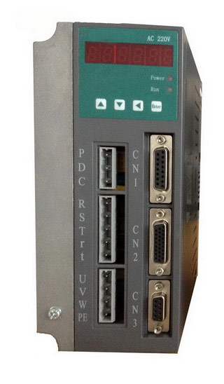 Gozuk synchronous ac servo drive is designed and manufactured, employing the advanced control algorithm based on the market demand, which can realize ...
A BLDC motor may have a trapezoidal Back EMF, there is something called Trapezoidal Motor Control Methodalogy (TRZ). TRZ is an extension of 6-step control ...
Permanent Magnet motors are more efficient than SCIM as the field in the rotor is permanently there. The big advantage for permanent magnet motors is in ...
Gozuk synchronous ac servo drive is designed and manufactured, employing the advanced control algorithm based on the market demand, which can realize ...
A BLDC motor may have a trapezoidal Back EMF, there is something called Trapezoidal Motor Control Methodalogy (TRZ). TRZ is an extension of 6-step control ...
Permanent Magnet motors are more efficient than SCIM as the field in the rotor is permanently there. The big advantage for permanent magnet motors is in ...