Wiki
An induction motor rotor can be either wound rotor or a squirrel cage rotor. The majority of commercial and industrial applications usually involve the use of a three-phase squirrel-cage induction motor. A typical squirrel-cage induction motor is shown. The rotor is constructed using a number of single bars short-circuited by end rings and arranged in a hamster-wheel or squirrel-cage configuration. When voltage is applied to the stator winding, a rotating magnetic field is established. This rotating magnetic field causes a voltage to be induced in the rotor, which, because the rotor bars are essentially single-turn coils, causes currents to flow in the rotor bars. These rotor currents establish their own magnetic field, which interacts with the stator magnetic field to produce a torque. The resultant production of torque spins the rotor in the same direction as the rotation of the magnetic field produced by the stator. In modern induction motors, the most common type of rotor has cast-aluminum conductors and short-circuiting end rings.
The AC induction motor is by far the most commonly used motor because it’s relatively simple and can be built at less cost than other types. Induction motors are made in both three-phase and single-phase types. The induction motor is so named because no external voltage is applied to its rotor. There are no slip rings or any DC excitation supplied to the rotor. Instead, the AC current in the stator induces a voltage across an air gap and into the rotor winding to produce rotor current and associated magnetic field. The stator and rotor magnetic fields then interact and cause the rotor to turn.
A three-phase motor stator winding consists of three separate groups of coils, called phases, and designated A, B, and C. The phases are displaced from each other by 120 electrical degrees and contain the same number of coils, connected for the same number of poles. Poles refer to a coil or group of coils wound to produce a unit of magnetic polarity. The number of poles a stator is wound for will always be an even number and refers to the total number of north and south poles per phase.
A three-phase motor stator winding consists of three separate groups of coils, called phases, and designated A, B, and C. The phases are displaced from each other by 120 electrical degrees and contain the same number of coils, connected for the same number of poles. Poles refer to a coil or group of coils wound to produce a unit of magnetic polarity. The number of poles a stator is wound for will always be an even number and refers to the total number of north and south poles per phase.
The main difference between AC and DC motors is that the magnetic field generated by the stator rotates in the case of AC motors. A rotating magnetic field is key to the operation of all AC motors. The principle is simple. A magnetic field in the stator is made to rotate electrically around and around in a circle. Another magnetic field in the rotor is made to follow the rotation of this field pattern by being attracted and repelled by the stator field. Because the rotor is free to turn, it follows the rotating magnetic field in the stator.
It illustrates the concept of a rotating magnetic field as it applies to the stator of a three-phase AC motor. The operation can be summarized as follows:
It illustrates the concept of a rotating magnetic field as it applies to the stator of a three-phase AC motor. The operation can be summarized as follows:
- Three sets of windings are placed 120 electrical degrees apart with each set connected to one phase of the three-phase power supply.
- When three-phase current passes through the stator windings, a rotating magnetic field effect is produced that travels around the inside of the stator core.
- Polarity of the rotating magnetic field is shown at six selected positions marked off at 60 degree intervals on the sine waves representing the current flowing in the three phases, A, B, and C.
- In the example shown, the magnetic field will rotate around the stator in a clockwise direction.
- Simply interchanging any two of the three-phase power input leads to the stator windings reverses direction of rotation of the magnetic field.
- The number of poles is determined by how many times a phase winding appears. In this example, each winding appears twice, so this is a two-pole stator.
In homogenizing manufacturing consistency, the National Electrical Manufacturers Association (NEMA) created a set of standards describing the various sizes of electric motors. NEMA frames are organized into groups where all mounting dimensions are identical.
 The reason for this system allows for substitution of a motor manufactured by one company with a different company, if the frame isn’t unique.
In an excellent article at the Electrical Engineering Portal, Edvard points out the seven common NEMA motor types:
1. Open Drip Proof (ODP)
Allows air to circulate through the windings for cooling, but prevent drops of liquid from falling into motor within a 15 degree angle from vertical. Typically used for indoor applications in relatively clean, dry locations.
2. Totally Enclosed Fan Cooled (TEFC)
Prevents the free exchange of air between the inside and outside of the frame, but does not make the frame completely air tight. A fan is attached to the shaft and pushes air over the frame during its operation to help in the cooling process.
The ribbed frame is designed to increase the surface area for cooling purposes.
The TEFC style enclosure is the most versatile of all. It is used on pumps, fans, compressors, general industrial belt drive and direct connected equipment.
The reason for this system allows for substitution of a motor manufactured by one company with a different company, if the frame isn’t unique.In an excellent article at the Electrical Engineering Portal, Edvard points out the seven common NEMA motor types:
1. Open Drip Proof (ODP)
Allows air to circulate through the windings for cooling, but prevent drops of liquid from falling into motor within a 15 degree angle from vertical. Typically used for indoor applications in relatively clean, dry locations.
2. Totally Enclosed Fan Cooled (TEFC)
Prevents the free exchange of air between the inside and outside of the frame, but does not make the frame completely air tight. A fan is attached to the shaft and pushes air over the frame during its operation to help in the cooling process.
The ribbed frame is designed to increase the surface area for cooling purposes.
The TEFC style enclosure is the most versatile of all. It is used on pumps, fans, compressors, general industrial belt drive and direct connected equipment.
First, 7 things to consider when choosing an electric motor:
Choosing the right motor isn’t always straightforward. There are so many variables to consider that it can be hard to know where to start. The wrong motor can result in a myriad of problems, and can ultimately cause application failure.
(Here are) some initial questions that you need to answer before attempting to find the right motor for your project.
Questions you need to consider in choosing a motor:
Speed: How fast should the motor be able to run? Torque: Which motors provide enough torque? Size: What are the size restrictions? Precision: Does the motor need to be accurate? How accurate? Environment: What is the environment in which the motor will be running (is there dust, moisture, air flow, etc.)? Communication: How do you want to communicate with the motor? Cost: What is your budget?
Once you’ve come up with answers to these preliminary questions, you can begin to figure out the best option for your application.
A high potential (hipot) test verifies that the insulation of an energized product or component is sufficient to protect the operator, system or connected components from electrical shock.
A typical electric wire has one or two components: a wire conductor along which the current flows, and insulation (aka dielectric) that shields the conductor from direct contact with other wires. Some wires also contain a third component, metallic shielding, between the conductor and the insulation. The question is: will the insulation do the job it was designed to do? If not, its failure could cause injury, loss of life, and damage to expensive equipment along with costly downtime.
A hipot test applies high voltage between a product's current-carrying conductors and its metallic shielding. The hipot tester measures current that flows through the insulation, known as dielectric leakage current. Hence, when a deliberate over-application of test voltage doesn't cause the insulation to break down (in other words if the insulation sufficiently withstands the voltage under normal operating conditions without allowing it to “leak out”), the product is considered safe under normal operating conditions.
There are two types of induction motors which have double rotor slots. In the first type, both slots, upper and inner, are filled with the same conducting material (aluminum for example) and as a consequence the motor has a single cage finally, despite the double rotor slots. In the second type, usually different materials are to fill the upper and inner rotor slots (for example aluminum for the upper slots and copper for the inner slots). So, in this category the motor has two electrically independent rotor cages.
The only way for the two windings of any type (coils OR bars) to be electrically independent is: 1) insulate each winding with some form of groundwall, and 2) leave the ends of the windings unconnected from each other.
In the case of most double-cage windings, there is some form of electrical pathway between the upper cage material (which is in direct contact with the lamination steel) and the lower cage (which is ALSO in direct contact with the lamination steel).
Usually, the choice for a double-cage arrangement boils down to optimization of the overall cage performance between two "standard" materials available to a manufacturer: one is often a high resistance material and the other is a low resistance material. When combined, the result is a somewhat-balanced "medium" resistance material.
I was doing some tests the other day on slow speed control (1rpm). I thought that sinusoidal commutation and a high resolution encoder (4K CPT) would be "the thing" for controlling a multi-pole flat motor well (with detent torque - naming the EC90 flat from maxon). This would enable the controller to have better control during the commutation between coil switching. During the commutation the natural attraction of the rotor to the poles pulls and pushes the rotor into position. This is something that I thought sinusoidal commutation would help with. I was pleasantly surprised that using another controller that had just block commutation but a 53.5Khz current loop proved far superior in comparison to the 10KHz control on the sinusoidal drive!
The communication is extremely important. If you just speak about the operation of let's say a drive and controller pair. But if you have all kinds of different applications, then additional aspects have to come into consideration.
* If you want to develop some feature that needs specification to be supported by several other vendors, then the democratic and continuously operation Technical Working Groups (TWG) will help you to realize this feature inside the next specification round.
* As soon as your planning the plant, you will think of how you build up you cabinets etc. Within a SERCOS plant you just need to think about the devices you have anyway. No switches required. Costs no money, needs no space, No reliability problem.
* When you start-up a plant, you will have some problems at one or the other corner (we all know that).
* Due to fast-ethernet your automation components will not suck up all the bandwidth and you will want to add standard Ethernet components. SERCOS has built-in 3-port switches that transfer the non-sercos Ethernet frames unchanged through the network, no more efficient way like this. There is no point in the network where standard-Ethernet devices can do any harm.
I am not a manufacturer of motors, except for the modification of specialty applications. For example we changed out several hundred motors for the National Weather Service contained in a dipole antenna body. Existing motor was a single phase permanent split capacitor synchronous motor, 110 volt, 1800 RPM DESIRED, due to a feedback tachometer mounted on the motor to verify the speed as these receivers accepted upper air feedback of weather conditions, from weather balloons launched two to three times a day. Location and tracking of the balloons were critical, if the tach feedback was off by one rpm [from 1800] the tracking electronics could not deal with the inconsistency.
I attempted to purchase motors for this application, but because the motor was mounted vertically in a solid cone, no ventilation, plus they were single phase, with induction synchronous rotors, voltage was a consideration, and the units were mounted from Hawaii to Guam to Florida, across the US and Territories.
I took the existing single phase PSC SYNCH MOTOR, which few ever had the torque, or would stay at 1800 rpm, or fail do to the heat.
While they only needed around 300 plus active motors, they needed half as many as spares, considering the past history of failures and the lack of ability to deliver accurate timely weather data over an exact path.
It was not a case of excessive NOISE, it was a case of perceived sound, it sounded different, so for those involved with any Governmental Agency knows that form, fit, function is their mantra and excuse to not accept anything.
We had several complaints of noise, turns out the noise was in no way a danger or at levels of any concern, just different.
While testing 4. 6. 8. 2 pole motors for "noise" in a controlled environment, is only data from those conditions, out in the wild west, those conditions are going to change, mounting, structure, all explained above will affect the motor's "noise" levels, or perceived "noise" levels.
In the fact that no load, [NEMA] testing is not going to be exacting as other possible more exacting, different parameter type testing, if noise is a concern, is under full load, which again is a variable.
A servo system is a servo system and so where or how it is used, not to oversimplify, it is almost irrelevant to a controls engineer. There are a lot of questions that would have to be answered before either myself or anyone with experience in controls could give you sound advice specific to your project:
This is just to get you started thinking about some basic issues. I have experience with motion controls, but I am not a motion controls expert. A motion controls expert will I am sure, come up with a much more comprehensive list of questions.
As far as servos, if you are looking to learn how to program motion controls, I suggest to look into Yaskawa. Spend a few hours perusing their website. Yaskawa products have very good reputation and they have a large installed base, and, I personally like their website. It has a lot of useful information. I like Allen-Bradley as well, but you should know that I am an Allen-Bradley integrator and channel partner, and so I am somewhat partial to their products. AB stuff is expensive anyway, but for good reason. One of my colleagues for whom I have tremendous respect, with a ton of experience in motion controls is very fond of Copley.
If you Google 'Motion Controls' you'll get a ton of hits and you should find some useful info there as well.
Generally speaking, in my opinion, a big part of anything involving motion; fault handling and recovery, and of course, safety. You absolutely must take safety into consideration when dealing with motion and make it a priority.
- Do you already have an EMAP Servo Press?
- Does it have a servo control system in it already?
- If it does, are you looking to integrate the Press with other automation devices?
- If it doesn't, how many axes do you need?
- Do you need a coordinated motion controller?
This is just to get you started thinking about some basic issues. I have experience with motion controls, but I am not a motion controls expert. A motion controls expert will I am sure, come up with a much more comprehensive list of questions.
As far as servos, if you are looking to learn how to program motion controls, I suggest to look into Yaskawa. Spend a few hours perusing their website. Yaskawa products have very good reputation and they have a large installed base, and, I personally like their website. It has a lot of useful information. I like Allen-Bradley as well, but you should know that I am an Allen-Bradley integrator and channel partner, and so I am somewhat partial to their products. AB stuff is expensive anyway, but for good reason. One of my colleagues for whom I have tremendous respect, with a ton of experience in motion controls is very fond of Copley.
If you Google 'Motion Controls' you'll get a ton of hits and you should find some useful info there as well.
Generally speaking, in my opinion, a big part of anything involving motion; fault handling and recovery, and of course, safety. You absolutely must take safety into consideration when dealing with motion and make it a priority.
Induction motors operate on the principal of current induction in the rotor which must rotate at a speed less than synchronous speed for induction to occur. This is referred to as slip speed and should not be confused with pole slipping.
Why induction motors have no pole slipping and why other motors have pole slipping. I will attempt to answer this but first let's define poles and synchronous speed in regards to electric motor operation.
Poles in an electric motor refer to the magnetic circuit poles and come in sets of two just like a common magnet. One is north (N) and one is south (S). If a motor has two poles, it will have one N-pole and one S-pole. If the motor has four poles, it will have 2 N-poles and 2 S-poles and so on.
Synchronous speed in an electric motor is the speed that is produced by the traveling magnetic filed wave as it rotates around the stator magnetic circuit. The synchronous speed of a motor is equal to 120*f/p where f = the system frequency in Hz and p is equal to the number of poles in the motor.
All AC motors have two basic parts: (1) a stator winding and iron core and (2) a rotor winding and iron core that is free to rotate and is connected to the motor shaft. For a 3-phase induction motor, when the stator is energized by a three phase voltage source, a magnetic field will be produced that rotates at synchronous speed. As this magnetic flux cuts across the rotor winding it induces a current (via Faraday's law of induction) in the rotor winding which intern produces a second magnetic flux. These two magnetic fluxes both rotate at synchronous speed and couple together like two magnets and thus transfer torque directly to the rotor shaft.
 Servo Motor & Drives
Category
Featured
 Assuming that you checked the mechanical properties and the centrifugal force at the rotor at the higher speed from 50Hz to 60Hz, and they are OK, then ...
The troubleshooting guide outlines a comprehensive variety of motor problems. Generally the categories are arranged according to symptoms offering brief ...
The main difference between AC and DC motors is that the magnetic field generated by the stator rotates in the case of AC motors. A rotating magnetic ...
First, 7 things to consider when choosing an electric motor: Choosing the right motor isn’t always straightforward. There are so many variables to ...
Induction motors operate on the principal of current induction in the rotor which must rotate at a speed less than synchronous speed for induction to ...
Assuming that you checked the mechanical properties and the centrifugal force at the rotor at the higher speed from 50Hz to 60Hz, and they are OK, then ...
The troubleshooting guide outlines a comprehensive variety of motor problems. Generally the categories are arranged according to symptoms offering brief ...
The main difference between AC and DC motors is that the magnetic field generated by the stator rotates in the case of AC motors. A rotating magnetic ...
First, 7 things to consider when choosing an electric motor: Choosing the right motor isn’t always straightforward. There are so many variables to ...
Induction motors operate on the principal of current induction in the rotor which must rotate at a speed less than synchronous speed for induction to ...
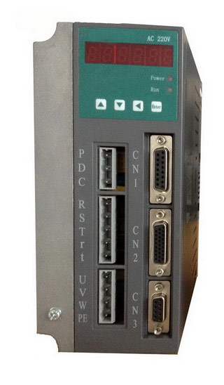 Gozuk synchronous ac servo drive is designed and manufactured, employing the advanced control algorithm based on the market demand, which can realize ...
A BLDC motor may have a trapezoidal Back EMF, there is something called Trapezoidal Motor Control Methodalogy (TRZ). TRZ is an extension of 6-step control ...
Permanent Magnet motors are more efficient than SCIM as the field in the rotor is permanently there. The big advantage for permanent magnet motors is in ...
Gozuk synchronous ac servo drive is designed and manufactured, employing the advanced control algorithm based on the market demand, which can realize ...
A BLDC motor may have a trapezoidal Back EMF, there is something called Trapezoidal Motor Control Methodalogy (TRZ). TRZ is an extension of 6-step control ...
Permanent Magnet motors are more efficient than SCIM as the field in the rotor is permanently there. The big advantage for permanent magnet motors is in ...