Motor
The capacitor-start motor is a modified split-phase motor. A capacitor connected in series with the starting winding creates a phase shift of approximately 80 degrees between the starting and running winding. This is substantially higher than the 45 degrees of a split-phase motor and results in a higher starting torque. Capacitor-start motors provide more than double the starting torque with one-third less starting cur rent than the split-phase motor. Like the split-phase motor, the capacitor start motor also has a starting mechanism, either a mechanical centrifugal switch or solid-state electronic switch. This disconnects not only the start winding, but also the capacitor when the motor reaches about 79% of rated speed.
The capacitor-start motor is more expensive than a comparable split-phase design because of the additional cost of the start capacitor. However, the application range is much wider because of higher starting torque and lower starting current. The job of the capacitor is to improve the starting torque and not the power factor, as it's only in the circuit for a few seconds at the instant of starting. The capacitor can be a source of trouble if it becomes short circuited or open-circuited. A short-circuited capacitor will cause an excessive amount of current to flow through the staring winding, while an open capacitor will cause the motor to not start.
The capacitor-start motor is more expensive than a comparable split-phase design because of the additional cost of the start capacitor. However, the application range is much wider because of higher starting torque and lower starting current. The job of the capacitor is to improve the starting torque and not the power factor, as it's only in the circuit for a few seconds at the instant of starting. The capacitor can be a source of trouble if it becomes short circuited or open-circuited. A short-circuited capacitor will cause an excessive amount of current to flow through the staring winding, while an open capacitor will cause the motor to not start.
A single-phase split-phase induction motor uses a squirrel-cage rotor that is identical to that in a three phase motor. To produce a rotating magnetic field, the single-phase current is split by two windings, the main running winding and an auxiliary starting winding, which is displaced in the stator 90 electrical degrees from the running winding. The starting winding is connected in series with a switch, centrifugally or electrically operated, to disconnect it when the starting speed reaches about 75 % of full-load speed.
Phase displacement is accomplished by the difference in inductive reactance of the start and run windings as well as the physical displacement of the windings in the stator. The starting winding is wound on the top of the stator slots with fewer turns of smaller-diameter wire. The running winding has many turns of large-diameter wire wound in the bottom of the stator slots that give it a higher inductive reactance than the starting winding.
Phase displacement is accomplished by the difference in inductive reactance of the start and run windings as well as the physical displacement of the windings in the stator. The starting winding is wound on the top of the stator slots with fewer turns of smaller-diameter wire. The running winding has many turns of large-diameter wire wound in the bottom of the stator slots that give it a higher inductive reactance than the starting winding.
Most home and business appliances operate on single phase AC power. For this reason, single-phase AC motors are in widespread use. A single-phase induction motor is larger in size, for the same horsepower, than a three-phase motor. When running, the torque produced by a single phase motor is pulsating and irregular, contributing to a much lower power factor and efficiency than that of a polyphase motor. Single-phase AC motors are generally available in the fractional to 10-hp range and all use a solid squirrel-cage rotor.
The single-phase induction motor operates on the principle of induction, just as does a three-phase motor. Unlike three phase motors, they are not self-starting. Whereas a three-phase induction motor sets up a rotating field that can start the motor, a single-phase motor needs an auxiliary means of starting. Once a single-phase induction motor is running, it develops a rotating magnetic field.
The single-phase induction motor operates on the principle of induction, just as does a three-phase motor. Unlike three phase motors, they are not self-starting. Whereas a three-phase induction motor sets up a rotating field that can start the motor, a single-phase motor needs an auxiliary means of starting. Once a single-phase induction motor is running, it develops a rotating magnetic field.
1. A rotating magnetic field is the key to the operation of AC motors. Give a brief explanation of its principle of operation.
2. Compare synchronous speed and actual speed of an AC motor.
3. Calculate the synchronous speed of a six-pole AC motor operated from a standard voltage source.
4. Why is the induction motor so named?
5. Outline the operating principle of a three-phase squirrel cage induction motor.
6. Explain what effect rotor resistance has on the operation of a squirrel cage induction motor.
7. How is the direction of rotation of a squirrel-cage motor reversed?
8. If, while a three-phase induction motor is operating, power to one phase of its squirrel cage is lost, what will happen?
The three-phase synchronous motor is a unique and specialized motor. As the name suggests, this motor runs at a constant speed from no load to full load in synchronism with line frequency. As in squirrel-cage induction motors, the speed of a synchronous motor is determined by the number of pairs of poles and the line frequency.
The operation of a typical three-phase synchronous motor can be summarized as follows:
The operation of a typical three-phase synchronous motor can be summarized as follows:
- Three-phase AC voltage is applied to the stator windings and a rotating magnetic field is produced.
- DC voltage is applied to the rotor winding and a second magnetic field is produced.
- The rotor then acts like a magnet and is attracted by the rotating stator field.
- This attraction exerts a torque on the rotor and causes it to rotate at the synchronous speed of the rotating stator field.
- The rotor does not require the magnetic induction from the stator field for its excitation. As a result, the motor has zero slip compared to the induction motor, which requires slip in order to produce torque.
The wound-rotor induction motor (sometimes called a slip-ring motor) is a variation on the standard cage induction motors. Wound-rotor motors have a three-phase winding wound on the rotor, which is terminated to slip rings. The operation of the motor can be summarized as follows.
- The rotor slip rings connect to start-up resistors in order to provide current and speed control on start-up.
- When the motor is started, the frequency of current flowing through the rotor windings is nearly 60 Hz.
- Once up to full speed, the rotor current frequency drops down below 10 Hz to nearly a DC signal.
- The motor is normally started with full external resistance in the rotor circuit that is gradually reduced to zero, either manually or automatically.
- This results in a very high starting torque from zero speed to full speed at a relatively low starting current.
- With zero external resistance, the wound-rotor motor characteristics approach those of the squirrel cage motor.
- Interchanging any two stator voltage supply leads reverses the direction of rotation.
An induction motor rotor can be either wound rotor or a squirrel cage rotor. The majority of commercial and industrial applications usually involve the use of a three-phase squirrel-cage induction motor. A typical squirrel-cage induction motor is shown. The rotor is constructed using a number of single bars short-circuited by end rings and arranged in a hamster-wheel or squirrel-cage configuration. When voltage is applied to the stator winding, a rotating magnetic field is established. This rotating magnetic field causes a voltage to be induced in the rotor, which, because the rotor bars are essentially single-turn coils, causes currents to flow in the rotor bars. These rotor currents establish their own magnetic field, which interacts with the stator magnetic field to produce a torque. The resultant production of torque spins the rotor in the same direction as the rotation of the magnetic field produced by the stator. In modern induction motors, the most common type of rotor has cast-aluminum conductors and short-circuiting end rings.
The AC induction motor is by far the most commonly used motor because it’s relatively simple and can be built at less cost than other types. Induction motors are made in both three-phase and single-phase types. The induction motor is so named because no external voltage is applied to its rotor. There are no slip rings or any DC excitation supplied to the rotor. Instead, the AC current in the stator induces a voltage across an air gap and into the rotor winding to produce rotor current and associated magnetic field. The stator and rotor magnetic fields then interact and cause the rotor to turn.
A three-phase motor stator winding consists of three separate groups of coils, called phases, and designated A, B, and C. The phases are displaced from each other by 120 electrical degrees and contain the same number of coils, connected for the same number of poles. Poles refer to a coil or group of coils wound to produce a unit of magnetic polarity. The number of poles a stator is wound for will always be an even number and refers to the total number of north and south poles per phase.
A three-phase motor stator winding consists of three separate groups of coils, called phases, and designated A, B, and C. The phases are displaced from each other by 120 electrical degrees and contain the same number of coils, connected for the same number of poles. Poles refer to a coil or group of coils wound to produce a unit of magnetic polarity. The number of poles a stator is wound for will always be an even number and refers to the total number of north and south poles per phase.
In homogenizing manufacturing consistency, the National Electrical Manufacturers Association (NEMA) created a set of standards describing the various sizes of electric motors. NEMA frames are organized into groups where all mounting dimensions are identical.
 The reason for this system allows for substitution of a motor manufactured by one company with a different company, if the frame isn’t unique.
In an excellent article at the Electrical Engineering Portal, Edvard points out the seven common NEMA motor types:
1. Open Drip Proof (ODP)
Allows air to circulate through the windings for cooling, but prevent drops of liquid from falling into motor within a 15 degree angle from vertical. Typically used for indoor applications in relatively clean, dry locations.
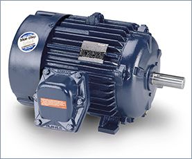
2. Totally Enclosed Fan Cooled (TEFC)
Prevents the free exchange of air between the inside and outside of the frame, but does not make the frame completely air tight. A fan is attached to the shaft and pushes air over the frame during its operation to help in the cooling process.
The ribbed frame is designed to increase the surface area for cooling purposes.
The TEFC style enclosure is the most versatile of all. It is used on pumps, fans, compressors, general industrial belt drive and direct connected equipment.
The reason for this system allows for substitution of a motor manufactured by one company with a different company, if the frame isn’t unique.In an excellent article at the Electrical Engineering Portal, Edvard points out the seven common NEMA motor types:
1. Open Drip Proof (ODP)
Allows air to circulate through the windings for cooling, but prevent drops of liquid from falling into motor within a 15 degree angle from vertical. Typically used for indoor applications in relatively clean, dry locations.
2. Totally Enclosed Fan Cooled (TEFC)
Prevents the free exchange of air between the inside and outside of the frame, but does not make the frame completely air tight. A fan is attached to the shaft and pushes air over the frame during its operation to help in the cooling process.
The ribbed frame is designed to increase the surface area for cooling purposes.
The TEFC style enclosure is the most versatile of all. It is used on pumps, fans, compressors, general industrial belt drive and direct connected equipment.
A high potential (hipot) test verifies that the insulation of an energized product or component is sufficient to protect the operator, system or connected components from electrical shock.
A typical electric wire has one or two components: a wire conductor along which the current flows, and insulation (aka dielectric) that shields the conductor from direct contact with other wires. Some wires also contain a third component, metallic shielding, between the conductor and the insulation. The question is: will the insulation do the job it was designed to do? If not, its failure could cause injury, loss of life, and damage to expensive equipment along with costly downtime.
A hipot test applies high voltage between a product's current-carrying conductors and its metallic shielding. The hipot tester measures current that flows through the insulation, known as dielectric leakage current. Hence, when a deliberate over-application of test voltage doesn't cause the insulation to break down (in other words if the insulation sufficiently withstands the voltage under normal operating conditions without allowing it to “leak out”), the product is considered safe under normal operating conditions.
After replacing the pump motor controller for the second time, we decided to find out what caused the controller to burn up. After operating for several days, we noticed excessive motor current on the controller. While we had the pump down for inspection, the customer technician removed and cleaned the filter screen. To continue our test we started the pump and the motor current was back to normal. What we learned was as the clogged filter screen increased the back pressure on the pump. To maintain the correct flow (pump speed) caused an increase in motor current to overcome the increased backpressure from the clogged filter screen. The motor current feedback was not included in the system diagnostics and the operators had not indication of the impending failure. The systems integrator undertook two improvement actions. (1) Increase the frequency at which all filter screens received cleaning and maintenance and (2) Brought the motor current value into an alarm to warn (predictive) the operators when a drive controller motor current was approaching and unsafe value. Why did the system integrator perform this work? Driven by the customer, the contract was written to require the system integrator to support the system for a pre-determined period of time after the system acceptance test.
Motors are commonly killed by one of two things: insulation failure or bearing failure. The dramatically simplified cause of these failures is heat and/or excessive voltage. The question is: How does use of a frequency inverter contribute to these failure modes, and how can these contributing factors be mitigated?
Motors are not 100 percent efficient, and require cooling. TEFC motors are cooled by a shaft-mounted fan. If a particular load application has a relatively high turndown ratio resulting in a very slow shaft speed, the cooling from the fan may be adversely affected. It cannot be assumed that a motor will accommodate an infinite turndown ratio without overheating its insulation system. Remember the "10 degree" rule of thumb discussed earlier. Motor manufacturers have recommended operation speed ranges for their motors. Operation restrictions on the turndown of the equipment connected to the motor should reflect these operation speed range recommendations.
As stated earlier, IGBTs can switch on and off extremely fast. The speed with which they can switch from 0 V to full dc bus voltage is referred to as rise time, or dv/dt. There is a phenomenon called "reflected wave" that is exacerbated by the IGBT's characteristic fast rise time (around 0.1 microseconds). The situation occurs when there is a mismatch between the interconnecting cable impedance and the motor. The motor terminals reflect the voltage rise back on the cable. This reflection on longer cable lengths can reinforce subsequence pulses, resulting in increasing electrical resonance as the carrier frequency is increased. This reflected wave can result in a voltage transient up to two times the dc bus voltage. Again, this dc bus voltage can be 1.414 times the ac input voltage. In a 480 V system, this can result in transients in excess of 1200 V. Faster rise times reduce the cable length at which this phenomenon is experienced. One manufacturer's general rule of thumb is that this can become an issue if cable length between the frequency inverter and motor exceeds 15 ft. In real-world applications, having this short of a length is pretty ambitious. Other manufacturers have recommendations for the maximum acceptable carrier frequency. Another recommended solution is to provide filtering devices between the frequency inverter and motor to mitigate the voltage overshoot, but that also adds cost and complexity.
 Servo Motor & Drives
Category
Featured
 Assuming that you checked the mechanical properties and the centrifugal force at the rotor at the higher speed from 50Hz to 60Hz, and they are OK, then ...
The troubleshooting guide outlines a comprehensive variety of motor problems. Generally the categories are arranged according to symptoms offering brief ...
The main difference between AC and DC motors is that the magnetic field generated by the stator rotates in the case of AC motors. A rotating magnetic ...
Assuming that you checked the mechanical properties and the centrifugal force at the rotor at the higher speed from 50Hz to 60Hz, and they are OK, then ...
The troubleshooting guide outlines a comprehensive variety of motor problems. Generally the categories are arranged according to symptoms offering brief ...
The main difference between AC and DC motors is that the magnetic field generated by the stator rotates in the case of AC motors. A rotating magnetic ...
 First, 7 things to consider when choosing an electric motor: Choosing the right motor isn’t always straightforward. There are so many variables to ...
Induction motors operate on the principal of current induction in the rotor which must rotate at a speed less than synchronous speed for induction to ...
First, 7 things to consider when choosing an electric motor: Choosing the right motor isn’t always straightforward. There are so many variables to ...
Induction motors operate on the principal of current induction in the rotor which must rotate at a speed less than synchronous speed for induction to ...
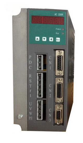 Gozuk synchronous ac servo drive is designed and manufactured, employing the advanced control algorithm based on the market demand, which can realize ...
A BLDC motor may have a trapezoidal Back EMF, there is something called Trapezoidal Motor Control Methodalogy (TRZ). TRZ is an extension of 6-step control ...
Permanent Magnet motors are more efficient than SCIM as the field in the rotor is permanently there. The big advantage for permanent magnet motors is in ...
Gozuk synchronous ac servo drive is designed and manufactured, employing the advanced control algorithm based on the market demand, which can realize ...
A BLDC motor may have a trapezoidal Back EMF, there is something called Trapezoidal Motor Control Methodalogy (TRZ). TRZ is an extension of 6-step control ...
Permanent Magnet motors are more efficient than SCIM as the field in the rotor is permanently there. The big advantage for permanent magnet motors is in ...